
|
|
|
| �ס�ҳ | ��е��ҵ��� | ���ӵ�����ҵ��� | �������ҵ��� | ��ľ���̱�ҵ��� | �Ӿ������ҵ��� | �������� | �Ŀ����� | �������� | �������� | ������� |
���������ڵ�λ�ã���ҳ >>�Ŀ����� >> �������� |
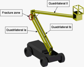
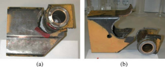
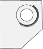
Fig. 4. Fractured bars of the lifting platform: (a) general view; (b) zoom view of the AC bar; (c) zoom view of the HP bar.
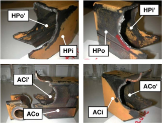
Fig. 5. Details of the fracture appearance and the adopted notations.
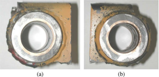
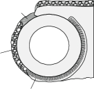
Fig. 6. Fracture zones in each bar: (a) HP bar; (b) AC bar.
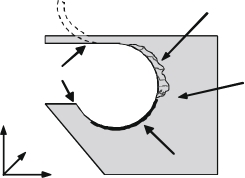
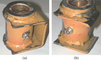
Fig. 7. View of the complete welding beads at outer surface for the bar-bearing joint: (a) HPo view; (b) ACo view. understanding of failure. This process usually has two steps. Firstly, a passing hole is made in the bar where the bearing will be placed, with a diameter somewhat bigger than that of the bearing itself. Probably, this hole was made by oxiacethilenic cutting. Later, the final step is performed: to place the bearing and to fix it to the bar by means of a bead welding process by voltaic arc. From the visual inspection of the outer surfaces of the bars (HPo, HPi, ACo and ACi) it appears that the welding bead (from now on referred to simply as ����bead��) extends completely along the circumferential joint of bar and bearing. On the opposite side the visual inspection of inner surfaces of the bars (HPo0 , HPi0 , ACo0 and ACi0 ) reveals that the bead is not completely extended along a circumference of the joint bar-bearing as it can be seen in Figs. 7 and 8. Results of the visual inspection in the fractured bars are sketched in Fig. 9, compared with the initial state of the unions before fracture.
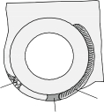
Fig. 8. View of the deficient welding beads at the inner surfaces for the bar-bearing joint: (a) HP bar; (b) AC bar. In particular, it was observed that the bead of bar-bearing joint in the interior of the HP bar extended along an arc of about 90��, so that this union present an arc of 270�� without any bound between bar and bearing. In the AC bar the inner beads were not complete as well, although the beads extended along a larger arc of about 180��. Visual analysis of the fracture surfaces confirmed that fracture initiated at the union of a bead with base material (i.e., with the bars). Then the crack grew by fatigue until it attained the critical length that prompted final fracture. The crack ini- tiation by fatigue is highlighted in Fig. 10, with a red paint, where the separation of the bead and the material base can be clearly appreciated. The same process was found at the bottom side of the picture in Fig. 10a. A fact should be pointed out: the presence of secondary cracks in the lateral sides in radial direction in relation to the bear- ing axis (Fig. 11). Such lateral quasi-straight cracks seem to be incubated starting from the main circumferencial cracks gen- erated by fatigue at the bar-bearing union. In addition, the afore-said lateral cracks appeared in both faces of the considered bars and grew in a through-the-thickness form. It could be observed that the surface cracks were bigger at the outer sides of the bars than in the inner ones. It may be assumed that these secondary lateral cracks were produced by fatigue. In addition, taking into account their situation between the main circumferential cracks and the final debonding of the welding region (Fig. 12), it seems to be reasonable to consider them as continuations of the initial circumferential cracks of the bead-bar joint, which deflect from the original propagation direction when the zone of high stress concentration is attained (Figs. 11b and 12). It is observed that the propagation of the main crack by fatigue has a branch in the advance direction when it reaches a micro-notch pro- duced during the extraction of material from the bar to allow the bearing to be placed (probably by oxiacethilenic cutting). 4. Discussion It appears that the lifting platform fracture started with the initiation of fatigue cracks (the afore-said main cracks) in those locations of the bar-bearing joints where an incomplete welding was performed at the inner sides of the bars, because only the outer welded seams were totally completed, whereas the inner welded seams were discontinuous (only about 50% of the seam was completed). This means a lack of lateral fastening of the bar-bearing joint, and a discontinuity (or slot) acting as an initial crack. Therefore, the bar-bearing union becomes weaker not only because the loss of constrain generated by the incompleteness of the welded seam, but, moreover, due to the notch effect (or crack-like effect) of the slot which produces stress concentration in this zone. In addition, thermal degradation of the steel was observed in the heat-affected zone (HAZ) near the welded seam. Fig. 13 shows the special microstructure in this zone, very different from that of the heat-unaffected microstructure of the base material (cf. Fig. 2) consisting of ferritic grains. The micro-hardness of this HAZ was measured, providing a value of 175 HV, quite higher than micro-hardness in the remote locations, i.e., of the base material. Thus microstructure alteration in the HAZ makes material therein harder and, consequently, more brittle and dangerous than in the rest of the lifting platform. Apparently, the initial crack grows in two directions: (i) mainly along the circumferential paths in the bead-bar welded joint; (ii) branches of lateral cracks in radial direction (cf. Fig. 12). The fracture surfaces of these lateral cracks (Fig. 14), when analyzed by SEM, showed typical fatigue striations in a direction perpendicular to the crack front advance (Fig. 15). This con- firms that this secondary cracking (leading to catastrophic failure) was driven by cyclic loading. Following the initial cracking by fatigue, a fracture surface can be found with a tearing appearance, which indicates a quite fast separation of the bead and the bar (base material). This zone has a brighter appearance that the previous fatigue cracking stage, probably due to the shorter time of exposure to the environment of this zone. Finally, when the circumferential fatigue crack along the welded seam in the bead attains a critical value, unstable crack propagation took place up to the global failure of the lifting platform, such a critical crack spreading approximately along
|
|||||||||||||||||||||||||||||||||||||||||||||||
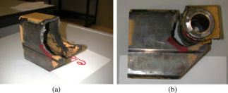 |
Fig. 10. Views of the HP bar and its bearing in the initiation zone of the fatigue cracking.
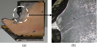
Fig. 11. Fatigue crack in radial direction in HPi bar.
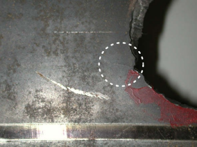 |
Fig. 12. Fatigue crack in radial direction in HPo bar.
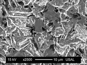 |
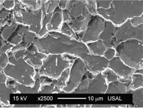
Fig. 13. Altered microstructure of the material in the heat-affected zone of the welding area.
180�� of the welding circumference (including both the initial fatigue crack and the tearing zone), as shown in Fig. 16. The appearance of such a tearing zone resembles the typical ductile fracture associated with low thickness specimens, as in the case of the bars of the lifting platform.
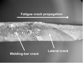
Fig. 14. Fatigue crack appearance.
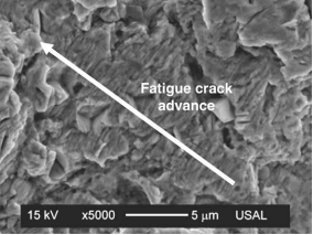 |
Fig. 15. Microfractography of the fatigue crack growth.
 Tear zone
Final Fracture
Side crack
y
z
FInaittiiaglaFaintiigcuieal
x
Fig. 16. Crack initiation and growth until final fracture.
5. Conclusions
The results of the failure analysis presented in this work lead to the following conclusions.
1. Failure analysis demonstrated that this catastrophic failure was produced by the deficiency (discontinuity) of the welding seam over the inner side of the bar at the circumferential bar-bearing joint, a critical location due to the very probable overstressing caused by the geometrical changes there (hole, corners, etc.) producing a sort of notch effect, promoting the initiation and propagation of fatigue cracks and posterior failure.
2. The discontinuity of the welding seam acted as a crack, slot or notch in the solid, thereby generating additional stress concentration and promoting (even more) fatigue cracking which finally resulted in the debonding between the bar and the bead along the welded joint.
3. The fatigue fracture process was enhanced in the welded area and surroundings due to the degradation of mechanical properties created by the welding procedure in the welded seam and in the heat-affected zone (HAZ). Such degradation was detected by micro-hardness measurements and metallographic analysis (negative effect of the weld).
4. Another factor promoting cracking in the bar-bead joint is the loss of constraint due to the lack of continuity of the weld- ing seam along the circumferential joint which causes over-bending and undesired rotations in the joint and thus a real increase of stress intensity factor in the cracked area (negative effect of the absence of weld).
5. Conclusions 3 and 4 seem to be paradoxical. On one hand, there is a negative effect of the weld (degradation of properties in the HAZ), and thus welding appears as a problematic action. However, on the other hand, there is a negative effect of the absence of weld (discontinuity of the welding seam creating crack and the subsequent loss of constraint in the joint). Thus welding seems to be good but, on the other hand, it is not so good (a Galician approach, associated with a special region in the North West of Spain where, when you see a person in a stair, you are never sure if he is going up or coming down, but this is another story). The real thing in that, in this case, welding did not produced its logical benefits (good joint and adequate constraint) but unfortunately generated its inevitable secondary effects (degradation of the properties in the HAZ). This is a proof of an inadequate manufacturing procedure which caused the failure of the lifting platform and a fatal accident.
Acknowledgement
Authors wish to express their gratitude to ����IBÉRICA DE PODAS® Y FORESTACIÓN, S.L.�� for the financial support of this work.
References
[1] Somers BR, Pense AW. Welding failure analysis. Mater Charact 1994;33:295�C309.
[2] Bhattacharyya S, Adhikary M, Das MB, Sarkar S. Failure analysis of cracking in wheel rims �C material and manufacturing aspects. Eng Fail Anal 2008;15:547�C54.
[3] Silveira E, Irisarri AM. Estudio de las causas de la rotura prematura de un ventilador e��lico. Anal Mec��n Fract 2008;25:769�C74.
[4] Torres Y, Gallardo JM, Dom��nguez J. Fractura fr��gil de un gancho de gr��a. Anal Mec��n Fract 2008;25:775�C80.
[5] Silveira E, Atxaga G, Erauzkin E, Irisarri AM. Estudio de las causas de la rotura prematura de un ��labe de turbina de aviaci��n. Anal Mec��n Fract 2007;24:551�C6.
[6] Hou C-Y. Fatigue analysis of welded joints with the aid of real three-dimensional weld toe geometry. Int J Fatigue 2007;29:772�C85.
[7] Cho H-N, Lim J-K, Choi H-H. Realiability-based fatigue failure analysis for causes assessment of a collapsed steel truss bridge. Eng Fail Anal 2001;8:311�C24.
[8] Norma B��sica de la Edificaci��n NBE EA-95. Estructuras de acero en edificaci��n. Madrid: Ministerio de Fomento; 1995 [in Spanish].
[9] Welding, Brazing, and Soldering. ASM handbook, vol. 6. San Jose, California, USA: ASM International; 2007.
[10] Failure Analysis and Prevention. ASM handbook, vol. 11. San Jose, California, USA: ASM International; 2007.
ȫ�ױ�ҵ��������ֳɳ�Ʒ��������ѯ�źţ�biyezuopinvvp QQ��1015083682 ������ҳ ��ת����ע����Դ��www.biyezuopin.vip| |
|
|
��һƪ���£���Ҷ������� ��������
|
��һƪ���£�����������ƽ̨�Ĺ��Ϸ���
|
 600
600 300
300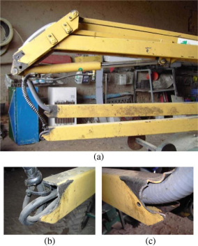

 BEFORE AFTER
 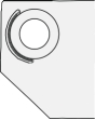 welding o
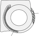 tear material
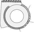 welding o
 tear
tear