A Clamping Design Approach for Automated Fixture Design
J. Cecil
Virtual Enterprise Engineering Lab (VEEL), Industrial Engineering Department, New Mexico State University, Las Cruces, USA
In this paper, an innovative clamping design approach is described in the context of computer-aided fixture design activi- ties. The clamping design approach involves identification of clamping surfaces and clamp points on a given workpiece. This approach can be applied in conjunction with a locator design approach to hold and support the workpiece during machining and to position the workpiece correctly with respect to the cutting tool. Detailed steps are given for automated clamp design. Geometric reasoning techniques are used to determine feasible clamp faces and positions. The required inputs include CAD model specifications, features identified on the finished workpiece, locator points and elements.
Keywords: Clamping; Fixture design

1. Motivation and Objectives
Fixture design is an important task, which is an integration link between design and manufacturing activities. The automation of fixture design activities and the development of computer-aided fixture design (CAFD) methodologies are key objectives to be addressed for the successful realisation of next generation manufacturing systems. In this paper, a clamp design approach is discussed, which facilitates automation in the context of an integrated fixture design methodology.
Clamp design approaches have been the focus of several research efforts. The work of Chou [1] focused on the twin criteria of workpiece stability and total restraint requirement. The use of artificial intelligence (AI) approaches as well as expert system applications in fixture design has been widely reported [2,3]. Part geometry information from a CAD model has also been used to drive the fixture design task. Bidanda
[4] described a rule-based expert system to identify the locating and clamping faces for rotational parts. The clamping mech- anism is used to perform both the locating and clamping functions. Other researchers (e.g. DeVor et al. [5,6]) have analysed the cutting forces and built mechanistic models for drilling, and other metal cutting processes. Kang et al. [2] defined assembly constraints to model spatial relationships between modular fixture elements. Several researchers have employed modular fixturing principles to generate fixture designs [2,7�C11]. Other fixture design efforts have been reported in [1,3,9,12�C23]. An extensive review of fixture design related work can be found in [21,24].
In Section 2, the various steps in the overall approach to automate the clamping design task are outlined. Section 3 describes the determination of the clamp size to hold a work- piece during machining and in Section 4, the automatic determi- nation of the clamping surface or face region on a workpiece is detailed. Section 5 discusses the determination of the clamp- ing points on a workpiece.
2. Overall Approach to Clamp Design
In this section, the overall clamping design approach is described. Clamping is usually carried out to hold the part in a desired position and to resist the effects of cutting forces. Clamping and locating problems in fixture design are highly related. Often, the clamping and locating can be accomplished by the same mechanism. However, failure to understand that these two tasks are separate aspects of fixture design may lead to infeasible fixture designs. Human process planners generally resolve the locating problem first. The approach developed can work in conjunction with a locator design strategy. However, the overall locator and support design approach is beyond the scope of this paper.
CAD models of the part design (for which the clamp design has to be developed), the tolerance specifications, process sequence, locator points and design, among other factors, are the inputs to the clamp design approach. The purpose of clamping is to hold the parts against locators and supports. The guiding theme used is to try not to resist the cutting or machining forces involved during a machining operation. Rather, the clamps should be positioned such that the cutting forces are in the direction that will assist in holding the part securely during a specific machining operation. By directing the cutting forces towards the locators, the part (or workpiece) is forced against solid, fixed locating points and so cannot move away from the locators.
The clamp design approach discussed here must be viewed in the context of the overall fixture design approach. Prior to performing locator/support and clamp design, a prelimi- nary phase involving analysis and identification of features, associated tolerances and other specifications is necessary. Based on the outcome of this preliminary evaluation and determination, the locator/support design and clamp design can be carried out. The clamp design approach described in this paper is discussed based on the assumption that locator/support design attributes have been determined earlier (this includes determination of appropriate locator and support faces on a workpiece as well as identification of locator and support fixturing elements such as V-blocks, base plates, locating pins, etc).
2.1 Inputs to Clamp Design
The inputs include the winged-edge model of the given product design, the tolerance information, the extracted features, the process sequence and the machining directions for each of the associated features in the given part design, the location faces and locator devices, and the machining forces for the various processes required to produce each corresponding feature.
2.2 Clamp Design Strategy
The main steps in the automation of the clamping design task are summarised in Fig. 1. An overview of these steps is as follows:
Step 1. Consider the set-up SUi in the set-up configuration list along with the associated [process I feature] entries.
Step 2. Identify the direction and type of clamping. The inputs required are the machining direction vectors mdv1,mdv2,
. . .,mdvn and identified normal vectors of support face nvs. If the machining directions are downward (which correspond to the direction vector [0, 0, -1]), and the normal vector of the support face is parallel to the machining direction, then the direction of clamping is parallel to the downward machining direction [0, 0, -1]. If sideways clamping is required, and if there are no feasible regions at which to position a clamp for downward clamping, then a side-clamp direction is obtained as follows. Let sv and tv be the normal vectors of the secondary (sv) and tertiary (tv) locating faces. Then, the direction of clamping used by a side-clamping mechanism such as a v- block should be parallel to both these normal vectors, i.e. the normal vectors of the each of the v-surfaces in the v-block will be parallel to sv and tv, respectively. The side clamping face should be a pair of faces parallel to the faces sv and tv, respectively.
Step 3. Determine the highest machining force from the mach- ining forces list (for each feature) MFi (i = 1, . . .,n). This will be the effective force FE that must be balanced while designing the clamp for this set-up SUi.
Step 4. Using the value of the calculated highest machining force FE, the dimensions of the clamp to be used to hold the
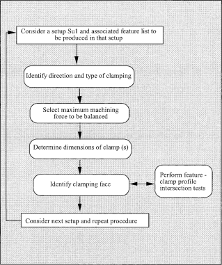
Fig. 1. The clamp design activities.
workpiece can be determined (for example, a strap clamp can be used as a clamping mechanism). The approach for this task is explained in Section 3.
Step 5. Determine the clamping face on a given workpiece. This step can be automated as described in Section 4.
Step 6. The actual position of the clamp on the clamping face is determined in an automated manner as explained in Section 5.
Consider next set-up SU(i + 1) and proceed to step 1.
3. Determination of the Clamp Size
In this work, the clamps used belong to the family of clamps referred to as strap clamps. A strap clamp is based on the same principle as that of the lever (see Fig. 2). In this section, the automated design of a strap clamp is described. The clamping force required is related to the size of the screw or a threaded device that holds the clamp in place. The clamping force should balance the machining force to hold the workpiece in position. Let the clamping force be W and the screw diameter be d. The dimensions of the various screw sizes for various clamping forces can be determined in the following manner. Initially, the ultimate tensile strength (UTS) of the material of the clamp (depending on availability) can be retrieved from a data library. Various materials have different tensile strengths. The selection of the clamp material can also be performed directly using heuristic rules. For example, if the part material is mild steel, then the clamp material can be low
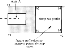
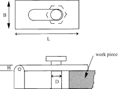 Fig. 2. The strap clamp.
carbon steel or machine steel. To determine the design stress, the UTS value can be divided by a safety factor (such as 4 or 5). The root area A1 of the screw (for a clamp such as a screw clamp) can then be determined: [Clamping force required/Design Stress DS]. Subsequently, the full area FA of the bolt cross-section can be computed as equal to {A1/(65%)} (since the root area of the screw where shearing can occur is approximately 65% of the total area of the bolt). The diameter of the screw d can then be determined by equating FA to (3.14 d2/4). Another equation which can be used involves relating the width B, height H and span L of the clamp to the screw diameter d (B, H, and L can be computed for various values of d): d2 = 4/3 BH2/L.
4. The Determination of the Clamping Face
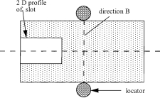
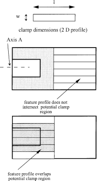
The required inputs to determine the clamping region include the CAD model of the product, the extracted features infor- mation, the feature dimensions and faces on which they occur, the locating faces and locators selected. Consider a potential clamping face PCF as shown in Fig. 3. The crucial criterion to be satisfied is that the clamping surface should not overlap or intersect with the features on that face, as shown in Fig. 4. The clamping surface area, which is in contact with the workpiece surface (or PCF) is a 2D profile consisting of line segments (see Fig. 6). By using line segment intersection tests, it can be determined whether the potential clamping area of contact overlaps any of the features on the given PCF.
The determination of clamping faces can be automated as fol- lows:
Fig. 3. Potential clamping face and feature profiles.
Fig. 4. Potential clamping face and clamp box profile.
Step 1. Identify faces that are parallel to the secondary and tertiary locator faces (lf1 and lf2) and at the farthest distance from lf1 and tcj, respectively. This is performed as shown below:
(a) Identify faces tci, tcj such that tci is parallel to lf1 and
tcj is parallel to lf2.
(b) Insert candidate faces tci in list TCF.
(c) By examining all faces tci listed in TCF, determine faces tci and tcj that are farthest from face lf1 and lf2, respect- ively, and discard all other faces from list TCF.
Step 2. Identify the face that is parallel to the location faces but not adjacent to the additional locator faces. It is preferable to select a clamp face that does not have to share the adjacent perpendicular face with a locator. This step can be automated as shown below:
(a) Consider each face tci in list TCF and obtain correspond- ing faces fci that are adjacent and perpendicular to each tci. Then, insert each face fci in list FCF.
(b) Examine each fci and perform the following test: If fci is adjacent, perpendicular to lf1 or lf2,
then discard it from list FCF and insert it in list NTCF. Step 3. Determine the clamping faces, based on the availability of potential clamping faces, as described below.
Case (a). If there are no entries in list NTCF, then use the faces in list TCF and proceed to step 4. If any faces were found that were perpendicular to the secondary and tertiary location faces lf1 and lf2, such faces are the next feasible choices to be used for clamping.
In this case, the only remaining choice is to re-examine the faces in list NTCF.
Case (b). If the number of entries in list NTCF is 1, the feasible clamping face is fci. The normal vector of the corresponding adjacent, perpendicular face tci is the axis of clamping.
Case (c). If number of entries in list NTCF is greater than 1, determine the face tci with larger area and proceed to step 4.
Step 4. Depending on the direction of clamping which is either [(+ or -)1, 0, 0] or [(+ or -) 0, 1, 0], the clamp can be positioned along the centre of the face tci. The candidate geometrical positions of the clamp can be determined using part geometry and topological information, which is described in the next section.
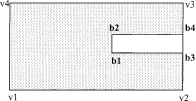
Fig. 5. Determination of the clamp profile dimensions.
5. Determination of the Clamping Points on a Clamping Face
After the clamp face has been determined, the actual clamping positions on that face must be determined. The inputs are the clamp profile dimensions, clamp directions [x, y, z], and poten- tial clamping face CF. The clamp profile dimensions are obtained (as in case (g)) using CF geometry as follows.
The first step is to determine a box size, which is tested to determine whether it contains any features inside it. Profile intersection tests can also be performed using the method described earlier. If the intersection test returns a negative result, then no feature intersects with the clamp box profile, as shown in Fig. 4. If the intersection test returns a positive result, the following steps can be performed:
1. Divide the clamp box profile into smaller rectangular strips of size (1 ´ w) (Figs 5 and 6).
2. Perform the intersection tests with the feature profiles of features that occur on the face CF for the given part design.
Fig. 6. Profiles intersection test of feature and clamp regions.
3. The rectangular strips, where no feature intersection occurs, are feasible clamping regions. If there is more than one candidate rectangle for clamping, the rectangle profile that is toward the mid-point of the CF face along the clamping axis is the clamp profile (and clamp points).
If no profile Pi can be found that does not intersect with the feature profiles, clamp width can be reduced by half and the number of clamps increased to two on that face. Using these modified clamp dimensions, perform the feature intersection test described earlier. If this test also fails, then the side face adjacent to the PCF can be used as the clamping surface to perform side clamping. The side face then becomes the PCF and the feature intersection test can be repeated.
5.1 The Intersection of Profiles Test
The required inputs include the 2D profile P1 another 2D profile P2. The intersection of profiles can be determined in an automated manner using the following approach. Each input profile Pi consists of a closed loop of line segments Lij. The steps in this profile test are as follows:
(T1) Consider a line segment L(i,1) in P1 and another line segment L(2, j) in P2.
(T2) For inputs L(i,1) and L(2, j), the intersection of edges can be employed. If the edge intersection test returns a positive value, then the feature profile intersects with the candidate or potential clamp profile under evaluation. If it returns a negative value, proceed to step 3.
(T3) Repeat step (T1) for the same segment or edge (Li,1) in
P1 with all remaining segments [(L2, j+1) till j = n�C1] in P2. (T4) Repeat steps (T1) and (T2) for the remaining edges or segments L12, L13,. . .,L1n in profile P1.
If the feature profiles overlap the clamping profiles, the line intersection tests will determine that occurrence. The inter- section of edges test can be performed automatically to detect whether two edges intersect with each other. The inputs required for this test are the line segments L12 {connecting (x1, y1) and (x2, y2)} and L34 {connecting (x3, y3) and (x4, y4)}.
Let the equation of L12 be represented by:
F(x,y) = 0 (1)
and that of L34 by:
H(x,y) = 0 (2)
Step 1. Using Eq. (1) compute r3 = F(x3, y3) by substituting x3 and y3 for x and y and compute r4 = F(x4, y4) by substitut- ing x4 and y4 for x and y.
Step 2. If r3 is not equal to 0, r4 is not equal to 0, and the signs of r3 and r4 are the same, (which indicate r1 and r2 lie on same side), then the edges L12 and L34 do not intersect. If this is not satisfied, then step (3) is performed.
Step 3. Using Eq. (2), compute r1 = H(x1, y1). Then, compute
r2 = G(x2, y2) and proceed to step 4.
Step 4. If r1 is not equal to zero, r2 is not equal to zero, and the signs of both r1 and r2 are the same }, then r1, r2 lie on
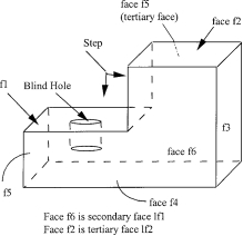
Fig. 7. Sample part to illustrate the clamping design approach.
the same side and the input line segments do not intersect. Else, if this condition is not satisfied, proceed to step 5.
Step 5. The given line segments do intersect. This completes the test.
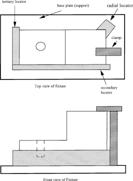
Consider the same sample part shown in Fig. 7. The features to be produced are a step and hole. Initially, the locator design is completed. The support locator (or primary locator) is a base plate (placed against face f4) and the secondary and tertiary locators are placed against faces f6 and f5 (which correspond to the locator faces lf1 and lf2 discussed in Section 4). An ancillary locator is also used, which is a v-block (positioned against the ancillary faces f3 and f5), shown in Fig. 8. Based on the steps outlined in the clamp design
Fig. 8. Fixture design for the sample part in Fig. 7.
approach discussed earlier, the candidate faces (which are parallel and at the farthest distance from lf1 and lf2) are face f3 and f5. There are no faces which are parallel to the locator faces but not adjacent to them. Using the priority rules in such cases (as discussed in step 3 of Section 4), the remaining candidate face is face f2. The clamp direction is downward; the v-block radial locator and other locators provide the required location with the clamp holding the workpiece down- ward against the baseplate.
The position of the clamp is determined based on the steps described in Section 5. As there are no feaures occurring on face f2, there is no need for feature intersection tests to determine collision-free clamping. The position of the clamp should be away from the v-locator (which is positioned along the ancillary location faces) as the clamping face is adjacent to the ancillary location faces (this ensures better access for quick clamping). The final location and clamping design is shown in Fig. 8.
The method discussed in this paper compares favourably with the other clamp design methods discussed in the literature. The uniqueness of the discussed approach is the systematic identification of the clamping faces based on part geometry, topology, and the occurrence of features to be machined. While other approaches have not exploited the position of the locators adequately, the proposed method uses the locators to hold the workpiece during machining against the primary, secondary, and tertiary locators. Another advantage of this approach is the determination of candidate feasible locations on clamp faces using the detection of profile intersections test (described earlier), which quickly and efficiently identifies potential down- stream problems which may occur during clamping and mach- ining of features.
6. Conclusion
In this paper, the clamping design aspects in the overall context of a fixture design methodology was discussed. The locator design, the part design specifications, and other inputs are considered in identifying the clamping faces and directions. The various steps to automate this approach are also discussed.
References
1. Y. C. Chou, V. Chandru and B. Barash, ��A mathematical approach to automatic configuration of machining fixtures: analysis and synthesis��, Transactions ASME, Journal of Engineering for Indus- try, 111(4), pp. 299�C306, 1989.
2. Y. Kang, Y. Rong and M. Sun, ��Constraint based modular fixture assembly modelling and automated design��, Proceedings of the ASME Manufacturing Science and Engineering Division, 8, pp. 901�C908, 1998.
3. M. Mani and W. R. D. Wilson, ��Automated design of workholding fixtures using kinematic constraint synthesis��, 16th NAMRC, pp. 437�C444, 1988.
4. B. Bidanda and P. H. Cohen, ��Development of a computer aided fixture selection system for concentric rotational parts,�� Advances in Integrated Design and Manufacturing, Proceedings 1990 ASME Winter Annual Meeting, San Francisco, CA, vol. 23�C1, pp. 151�C 162, 1990.
5. R. E. DeVor, V. Chandrasekharan and S. G. Kapoor, ��Mechanistic model to predict the cutting force system for arbitrary drill point geometry��, Transactions ASME Journal of Manufacturing Science and Engineering, 120, pp. 563�C570, 1998.
6. R. E. DeVor, S. G. Kapoor and W. J. Endres, ��A dual based approach to the prediction of machining forces for metal cutting processes: Part II, Model validation and interpretation��, Trans- actions Journal of Engineering for ASME Industry, 117, pp. 534�C 541, 1995.
7. M. V. Gandhi and B. S. Thompson, ��Automated design of modular fixtures for flexible manufacturing systems��, Journal of Manufac- turing Systems, 5(4), pp. 243�C252, 1987.
8. T. S. Kow, A. Senthil Kumar and J. Y. H. Fuh, ��An integrated computer aided modular fixture design system for interference free design��, Proceedings of the ASME Manufacturing Science and Engineering Division, 8, pp. 909�C916, 1998.
9. Y. Rong and S. Wu, ��Automated verification of clamping stability in computer aided fixture design��, Computers in Engineering, Proceedings of the International Conference, ASME, NY, pp. 421�C 426, 1994.
10. Y. Rong and Y. Bai, ��Machining accuracy analysis for computer aided fixture design��, Journal of Manufacturing Science and Engin- eering, 118, pp. 289�C300, 1996.
11. Y. Wu, Y. Rong and W. Ma, ��Automated modular fixture plan- ning: geometric analysis��, Robotics and Computer Integrated Manufacturing, 14, pp. 1�C15, 1998.
12. J. R. Boerma and H. J. J. Kals. ��Fixture design with FIXES��, Annals CIRP, 38, pp. 399�C402, 1988.
13. W. Cai, S. J. Hu and J. X. Yuan, ��A variational method of robust fixture configuration design for 3D workpieces��, Journal of Manufacturing Science and Engineering, 119, pp. 593�C602, 1997.
14. J. A. Cecil, ��Fixture design in a CIM environment, PhD disser- tation, Texas A&M University, Department of Industrial Engineer- ing, College Station, 1995.
15. J. Dai, A. Y. C. Nee and J. Y. H. Fuh, ��An approach to automating modular fixture design and assembly��, Proceedings of the Institution of Mechanical Engineers, Part B, Journal of Engin- eering Manufacture, 211, pp. 509�C521, 1997.
16. A. R. Darvishi and K. F. Gill, ��Knowledge representation database for the development of a fixture design expert system��, Proceed- ings of IMechE, 202, pp. 37�C49, 1988.
17. W. Ma, J. Li and Y. Rong, ��Development of automated fixture planning systems��, International Journal of Advanced Manufactur- ing Technology, 15(3) pp. 171�C181, 1999.
18. A. Y. C. Nee, K. Whybrew and A. Senthil Kumar, Advanced Fixture Design for FMS, Springer-Verlag, 1995.
19. Y. Rong, Y. Wu, W. Ma and S. LeClair, ��Automated modular fixture design: accuracy analysis and clamping design��, Robotics and Computer Integrated Manufacturing, 14, pp. 1�C15, 1997.
20. Shah and M. Mantyla, Parametric and Feature Based CAD-CAM: Concepts and Technology, John Wiley, New York, 1995.
21. B. S. Thompson and M. V. Gandhi, ��A literature survey of fixture design automation��, International Journal of Advanced Manufacturing Technology, pp. 240�C255, 1985.
22. A. J. C. Trappey and C. R. Liu, ��Automated fixture configuration using projective geometry approach��, International Journal of Advanced Manufacturing Technology, Vol. 8, pp. 297�C304, 1993.
23. K. Wright and C. C. Hayes, ��Automated planning in the machining domain, knowledge based expert systems for manufacturing��, ASME, PED-24, pp. 221�C232, 1986.
24. J. A. Cecil, ��Initiatives in computer aided fixture design��, VEEL Laboratory Report, Utah State University, January 2000.