Jounal of matenals processing technology 63 (1997) 881-886
Experiment and study into the axial drifting of the cylinder of a welding rollerbed
Fenggang shen ,xide pan ,jin xue
Welding research instiute ,xi`an jiaotong university. Xi`an .shaanxi province 710049.P.R.china
Abstract
The basic theory of the axial drifting of the cylinder of a welding roller bed is introduced in the paper,and at the same time experiment and study on the mechanism of the axial drifting of the cylinder have been done on an experimental model of the welding roller bed . It is shown that the main cause of the axial drifting of the cylinder lies in the existence of a spiral angle between the cylinder and the cylinder and the roller . the relative axial motions between the roller and the cylinder are compose of spiral motion,elastic sliding and frictional sliding. The theory of compatible motion and non-compatible motion is put forward for the axial motions of the cylinder .the relative axial motions of the cylinder . The relative axial motion between the rollers and the cylinder is coordinated by elastic sliding and frictional sliding between them
Keywords: welding roller bed; cylinder ; roller ; axial motion ; spiral angle
1 Introduction
In welding production, the assembly and circular seam welding of rotary workpieces, such as a boiler, a petrochemical pressure vessel and so on, are conducted on ;a welding roller bed. When rotating On a welding roller bed. The cylinde will inevitably produce axial drifting due to manufacturing, assembling tolerance of the welding roller bed and the cylinder’s surface irregularity (divergiug froman ideal rotary workpiece), thus the welding procedure may not be carried out successfully. It is necessary, therefore, to study the mechanism of the axial drifting of the cylinder to solve the problem of the axial drifting of the cylinder in circumferential welding. The results of the research will benefit the studying and designing of antidrifting welding roller bed. especially the analysis of the applied forces on the bed, and lead to determining the manufacturing and assembling tolerance of the bed, and providing the basis of theory for the mechanical adjusting mode to avoid axial drifting, the adjusting mode of closed circuit in the control circuit, and the selection of the adjusting value.
2. Theoretical analysis
2.1. Welding roller bed and cylinder
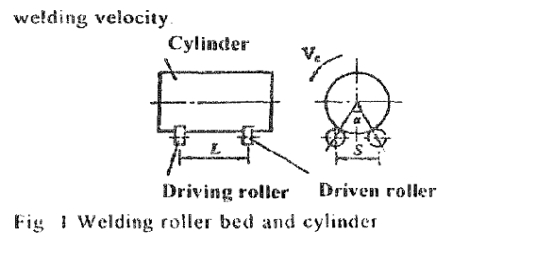
A welding roller bed is generally composed of four rollers. Driven by the driving roller, the cylinder makes a rotary uniform motion around its axis(shown in Fig. I), during which the circumferential welding procedure is carried out In Fig.1, a is the central angle, S is the supporting distance, L is the span of the roller. and V, is the circular linear velocity of the cylinder, also named the welding velocity2.
The axis of the cylinder will be not parallel to that of a roller if the roller is deflected by a certain angle from the deal position, or if the centers of the four rollers lie in the vertices of a simple quadrilateral, or if the centers of the four rollers are not on the same plane, or if the circu- larity of the cylinder is irregular because of deviation in manufacturing and assembling. Thus. the cylinder will nevitably move along its axis when rotating on a bed the contact of the cylinder and a roller can be cansidered as point contact if cytinder’s axis and roller’s axis do not lie in the same plane. Suppose P is the point of contact. the cylinder’s normal plane A is defined by the plane on which are the cylinder’s axis and generatrix n across the point of tangency on the cylinder (shown in fig2) makea cylinder’s tangent plane B across point P. Thus, plane A is vertical to plane B. lc is a cylinder’s tangent across P and lies in plane B. Ir is the roller’s tangent across the same point P, and lies in plane B also. In general, θ is defined as the axial deviation angle between the rol!er’saxis and the cylinder’s axis; β is defined as the spiral angle between generatrix n and m’ . a projective line obtained by projecting the roller’s generatrix m across point p on plane B and γ is defined as the projective angle between n and m , a projective line obtained byprojecting m on plane A. Fig. 3 indicates that the rela- tionship amongst the three angles is tanβ = tan2θ - tan 2γ
In Fig. 3, SB, Sθ and Sγ, are called the spiral displace-ment vector, the axial deviation displacement vector and the projective displacement vector respectively. their
relationship being:
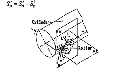
Fig. 2 Geometric relationship between the cylinder and an individual roller
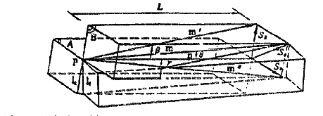
Fig. 3 Relationship between the angle vector and the displacement vector
2.2.2 relative axial motions relationship
(1)spiral motion2.
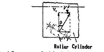
Fig. 4 Component of axial velocity
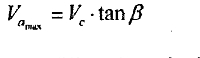
Because the roller’s axis is not parallel to the cylin- der’s central line, there is a spiral angle β between Vr,. and Vc, on the point of contact (shown in Fig. 2). When the roller and cylinder rotate synchronistically around their own axes, driven by tangential frictional force. a spiral effect will occur because of the different linear velocity direction between the roller and the cylinder at point P of contact The cylinder has a component of axial velocity,
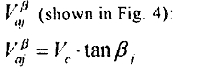
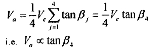
where Vc is the circular linear velocity of the cylinder.  is the cylinder’s axial component velociry exerted by single roller, and j can be 1. 2, 3, 4, representing the four rollers, respectively.
(2) Elastic sliding
Because of the existence of a spiral angle, an axial force Faj acts on cylinder. When the force is less than the maximum axial frictional force fNj (where f is the frictionfactor, and Nj is the normal pressure between a single roller and the cylinder), the cylinder will slide elastically over the roller along the axial direction[2~3] The component of the sliding velocity is.
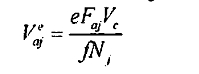
where e is the elastic sliding factor for metallic roller. e=O.OOl ~~ 0.005.
(3) Frictional sliding
When Faj is greater than the maximum frictional force fNj, the cylinder will make a frictional sliding over the roller. The sliding resistance is fNj[3]. The component of the frictional sliding velocity on Cylinder is Vaj the magnitude and direction of which can be determined by the universal relationship between the cylinder and the four rollers Frictional sliding will lead to the wear and tear of the surface of the cylinder and the rollers. which is unexpected in welding production When the cylinder drifts, above three kinds of motion do not occur simultaneously ‘I’hereforc. the axial drifting velocity of the cylinder is not the algebraic sum of the three components of velocity In the case of elastic sliding, the axial velocity is.
2.3 axial motion of the cylinder on a welding roller bed
2.3.1 Axial compatible motion
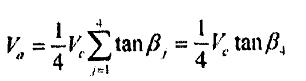
Under ideal conditions, when spiral angles βj between the cylinder and the four rollers are all the same, that is:β1=β2=β3=β4=βthe cylinder will move its compatible spiral motion. Two categories can be classified to analyze the axial motion of the cylinder:
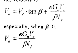
(I) When there does not exist an axial component due to gravity. the cylinder’s axial drifting velocity is:
Va=Vc * tanβ
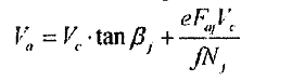
(2) When there exists an axial component of gravity Ga there exists an axial force on the cylinder. Now, the axial forces exerted on the four rollers have the same directional
And magnitude, the value being equal to Ga besues the component of spiral vetocity, there exist component of elastic on the cylinder the cylinder`s axial drifting velocity is
2.3.2.axial non-compatible motion
In general. spiral angles βj between the cylinder and the four rollers are not equal to each other in size and direction. i .e. the geometric relationships between the cylinder and the four rollers are all inconsistent Therefore, the components of the cylinder’s axial velocity against four rollers (i.e Vc *taβj) are not identical to each another. The cylinder will move with axial nompatible motion The axial velocities of the cylinder againsa the four rollers should be the same because the cylinder is considered as a rigid body as a whole and it has only one axial velocity. However. for some roller, Vc . tanβj and the cylinder’s real axial velocity are not likely to be the same, so an axial frictional force almost certainly appears between this roller and the cylinder The following two categories can be classified to discuss the non-compatible axial motion of the cylinder according to Ihe frictional force’s magnitude:
(I) When the axial frictional forces erected by each roller and the cylinder are all less than the maximum axial the action of the cylinder against the frictional force the action of the cylinder against the rollers produces elastic sliding The axial motion betweenan individual roller and the cylinder is coordinated by their elastic sliding
when the axial velocity of the cylinder is constant, the algebraic sum of cylinder’s axial forces erected by four rollers should be zero if rhe axial component of gravity is ignored. i.e.
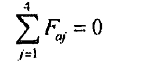
and there is little difference amongst Nj, against the four rollers, so that they can be approximately regarded as the same. Thus:
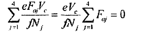
according to the above two equations, the axial drifting velocity of the cylinder is.
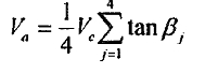
Where 0.25∑Tanβt represents the intrinsic attributes of the welding. Other bed under the condition that only the cylinder against all rolls produces elastic sliding this may be called the spiral rate of the cylinder`s spiral motion
(2) When the axial frictional force erected by some roller and the cylinder is greater than the maximum axial frictional force, frictional sliding occurs between the cylinder and this roller Then. the maximum axial force is acting on the bearing of the roller, its value being
Ffmax=fFNfmax
Because of the esistence of this frictional sliding. the Axial motion between an individual roller and the cylinder is not coordinated by their elastic sliding Now the axial non-compatible motion of the cylinder is determined by
the relative relationships between the cylinder and the four rollers. It is difficult to write a general compatible equation of the cylinder’s axial drifting velocity because this kind of condition is very complex. The following is further analysis and discussion of the problem At first, for ease in analyzing problem, the spiral angle average is defined as
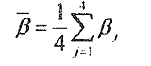
and the relative spiral angle as
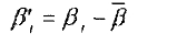
Arrange ,β1 in the order from big to smll and then from posirive to negative, expressed as β(j). then β1≥β2≥β3≥β4
Similarly, the normal force between the cylinder and a roller can be expressed as N(j). and the axial force as
Fj≤fNj
In general, the axial motion of the cylinder determined by the spiral angle average β is definel as the compatible component of the axial motion, is velocity being
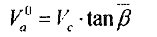
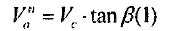
The axial motion of the cylinder determined by the relative spiral angle βj is defined as the non-compatible component of axial motion, its velocity being expressed asVa\n Analysis shows that Va`` is determined by the equilibrium condition the four roller axial forces when the cylinder moves along axial direction at a constant velocity. where not taking into account of the function of gravity’s axial component. Supposing that the cylinder makes a non-compatible component of axial motion with the maximum relative spiral angle β(I). its velocity is
Then the four axial forces can not be in equlibrium .i.e
F1-(F2+F3+F4) ≤0
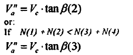
Because there is little difference amongst four normal forces, the four axial farces are also determined by normal force and the friction factor any axial force undoubtedly being less than the sum of the other three forces. Otherwise, if the cylinder makes a non-compatible component of axial motion with the minimum relative spiral angle β(4). its velocity is.
Va” = Vc * tanβ(4)
Similarly. four axial forces can not be in equilibrium also, i.e. :
[F(l) + F(2) + F(3) J - F(4) > 0
Therefore, the cylinder can only be approximately considered as making a non-compatible component of axial motion with the second or third relative spiral angle, i.e.:
In whatever case as expressed above. when the cylinder make a non-compatible component of axial motion, thetwo rollers having a greater velocity are driving rollers,and the other two rollers having a lesser velocity are resistant rollers, the equilibrium condition of axial forces being operative, i.e.:
F(1) + F(2) = F(3) + F(4)
According to the analysis above, and because of the unstability of friction factor f that is affected by the factors of load, material, condition of the contact surface, and circumstance, the non-compatible component Va of the axial velocity of the cylinder is undefined. When the cylinder makes a non-compatible axial motion, its axial velocity is composed of a compatible component Va\0 and a non-compatible component Va\n i.e
Va=Va\0+Va\n
Va=Va\0+Va\n
The most optimal adjustment of the axial motion is to make the non-compatible component as small as possible according to the stability of adjustment and decrease in axial force. No matter whether the cylinder makes compatible or non-compatible motion, supposing that the cylinder is ideal, its axial velocity is always existent and definable for a particular bed, its magnitude and direction reflecting the bed’s inherent property.
3. Experiment
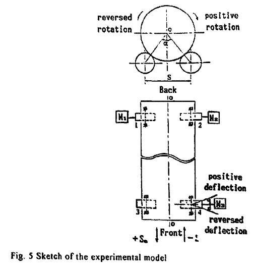
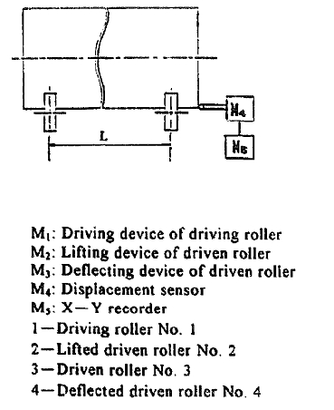
3.1. Descriphm of experment
The experimental model is shown in Fig 5. Experiments were done to study two factors: the spiral angle and the cylinder’s circular linear velocity, which affect the axial drifting of the cylinder. In the experimenting process. the axial displacement Sa and the axial drifting velocity Va of the cylinder were measured by the variation of the two
factors described above. The measuring method is shown in Fig. 5, and is carried out by means of bringing an axial displacement sensor into contact with one end of the cylinder. with the sensor being connected to an X-Y recorder to record the cylinder’s axial displacement every 5s. Linearly regressing the plot Sa--t (t expresses time), the average drifting velocity Va, at every deflecting angle can be calculated.
Before experimenting. the experimental model is initialised as follows: first. the height of the four rollers is adusted by means of a level to put the centers of the four
rollers in the same horizontal plane, and at the four vertexes of the rectangle. then the rollers are deflected so that the rotating cylinder is at the relative equilibrium position. Then the cylinder does not drift over a long time. or periodically drift over a very small axial range
3.2 experiment results and discussion
3.2.1 Effect of spiral angle (I) Fig. 6 shows that change of Va with the variation ofThe testing condition is: positive rotalion, Vc=35m/h
L=422mm, α=60”
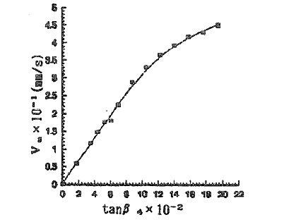
The Va-tanβ4 curve shows that Va is directly proportional to tanβ4 whenβ4 is relatively small (1~~~6c ). The slope of the line being 3. 06 mm/s, Va is no longer direclly proportional to tanβ4 when β4, is greater than 6C The curve is an arched curve. i. e . with the increment of β4,.Va, increases. but with the increment of Va gradually becoming smallet Because only one driven roller (roller No. 4) is deflected, i.e β4 can be changed whilst the others remain zero, the cylinder makes a non-compatible motion. When β4 is relatively small, Va is small also. The axial frictional forces between the cylinder and rollers are less than the maximum axial frictional force, and the cylinder produces an elastic sliding against rollers. Axial motion between each roller and the cylinder is coordinated by elastic sliding. thus Va is:
in the theoretical curve, the slope K’ can be calculated by the following equation:
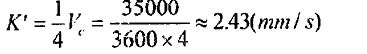
K=3.06mm/s in the experimental curve. Thus, in taking account of the experimental tolerance, the two slopes can be considered to be approximately equal. When β4 is relatively large, the axial frictional forces between the cylinder and the rollers are larger than the maximum axial frictional Force, and cylinder produces frictional sliding against the rollers Because of Ihe existence of sliding frictional resistance. Va is no longer lincarty increased with the increment of tanβ4 With the increment of tanβ4 the increment of V a; with gradually become smaller
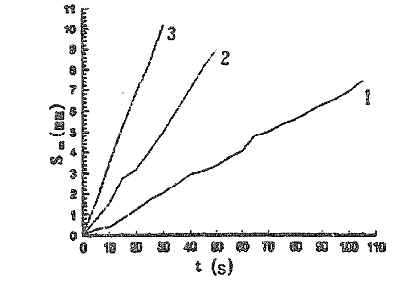
(2) The following three experiments were arranged to study the cylinder’s non-compatible axial motion further, deflecting positively one roller. two rollers and three rollers by the same spiral angle to measure three curves between Sa and v The experimental results are shown in Fig 7. With the increment in the number of deflected rollers, Va becomes greater. i e Va 3 > Va 2 > Va1
When the number of driven rollers deflected is varied, the degree of the cylinder’s non-compatible axial motion will be changed. With the increment of the number of lollers deflected by the same spiral angle. the compatible component becomes greater, but the non-compatible component becomes smaller. In other words, the cylinder’s axial motion will be transformed from noncompatible motion to compatible motion. Thus, Va becomes greater also, ultimately, being equal to the compatible axial velocity determined by the spiral angle β Now. the four rollers have the same spiral anyle β. So that Va is:
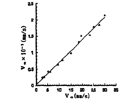
3.2.2 effect of circular linear velocity
Deflecting driven roller No 4 to a spiral angle of +2”from the equilibrium position, the cylinder will suffer axial drifting, Fig. 8 shows the Va-Vc curve, which latter indicates that Va is directly proportional to Vc, the slope of the curve being approximately 0.00708 because β4=+2 is too small, the cylinder does not make frictional sliding against each roller. Thus, the relative axial motion between the roller and the cylinder is completely coordinated by their elastic sliding, so that Va is
I. e .Va is directly proportional to Ve For the theoretical Curve the slope K * can be calculated by the following equation K”=0.25tanβ4= 0.25tan2'=0.00873 where K=0.00708mm/s in the experimental curve. Thus, in taking account of the experimental tolerance, the two slopes can be considered to be approximately equal.
4 Conclusions
1. Because of the deviations due to manufacturing and assembling. the cylinder’s central line and the roller’s axis are not parallel. i. e , they are not in the same plane, and there is a spiral angleβ at thc point of contact between the cylinder and the roller in the circular linear velocity direction. The existence of βis the basic reason for the occurrence of axial drifting. The effect of gravity in cylinder’s axial direction is also one of reasons for drifting.
2. The relative axial motions between an individual roller and the cylinder are composed of spiral motion. elastic sliding and frictional sliding When axial frictional sliding does not occur between the cylinder and a single
roller, the relative axial motion between the rollers and the cylinder is completely coordinated by their elastic sliding, Va is directly proportional to
When axial frictional sliding occurs between the cylinder and a roller. the relative asial motion between therollers and the cylinder will be commonly coordinated by elastic sliding and frictional sliding. but Va is not
directly proportional to
3 The axial motions of the cylinder can be divided intocompatibleand non-compatible motion There will be large axial forces acting on the bearings of the rollers, which will cause the wear and tear of the contact surfaces of the rollers and the cylinder, when non-compatible motion exists The non-compatible component of the axial motion is undefined however. the cylinder’s axial velocity is always existent and definable for a particular bed, its magnitude and direction reflecting the bed’s inherent property.
4 The reasonable adjustment of the axial motion is to make the non-compatible component as small as possible and the compatible component as large as possible.
5 With the increment of the number of rollers deflected by the same value of β the compatible component of axial velocity increases, but the non-compatible component decreases. With the increment of the compatible component, the velocity of axial drifting of the cylinder increases.
References
(1) Z Wang(ed ). teaching material on welding machinery Equipment Gansu university of Technology lanzhou P R china (1992) pp 85-98
(2)Wuhan lnstitulcof Buildins Materials and TechnologyI Tongi Universily. Nanjing Institute of Chemical Engineering, and Huanan Institute of Technology. Cement Producing machinery equipment, Architectural Industrial Publishing House of China, Beijing, (1981) pp, 184-187
(3)J . Halling(ed.). Principles of Trilrology The Macmillan Press, (1975) pp. 174-200
