| 设计 任务书 文档 开题 答辩 说明书 格式 模板 外文 翻译 范文 资料 作品 文献 课程 实习 指导 调研 下载 网络教育 计算机 网站 网页 小程序 商城 购物 订餐 电影 安卓 Android Html Html5 SSM SSH Python 爬虫 大数据 管理系统 图书 校园网 考试 选题 网络安全 推荐系统 机械 模具 夹具 自动化 数控 车床 汽车 故障 诊断 电机 建模 机械手 去壳机 千斤顶 变速器 减速器 图纸 电气 变电站 电子 Stm32 单片机 物联网 监控 密码锁 Plc 组态 控制 智能 Matlab 土木 建筑 结构 框架 教学楼 住宅楼 造价 施工 办公楼 给水 排水 桥梁 刚构桥 水利 重力坝 水库 采矿 环境 化工 固废 工厂 视觉传达 室内设计 产品设计 电子商务 物流 盈利 案例 分析 评估 报告 营销 报销 会计 |
|
|
|
| 首 页 | 机械毕业设计 | 电子电气毕业设计 | 计算机毕业设计 | 土木工程毕业设计 | 视觉传达毕业设计 | 理工论文 | 文科论文 | 毕设资料 | 帮助中心 | 设计流程 |
您现在所在的位置:首页 >>文科论文 >> 文章内容 |
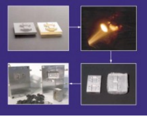
* austenitized at 1010°C, double tempered (2hr+ 2hr) at 590°C. ‡ no yield at 0.2% offset. Summary・ Spray forming is a robust rapid tooling technology that allows tool steel molds and dies to be produced in a straightforward manner. By coupling spray forming with commercial RP technology, turnaround time for tool steel molds and dies can be significantly reduced. ・ Rapid solidification of H13 tool steel results in the suppression of carbide precipitation and growth. ・ Properties of spray-formed H13 can be tailored by artificial aging or conventional heat treatment. ・ Hardness and strength of spray-formed/aged H13 compare favorably with forged/heat treated commercial material. References[1] R. G. W. Pye, Injection Mould Design, John Wiley & Sons, NY, p. 14, 1989. [2] Rapid Prototyping & Tooling State of the Industry - 1998 Worldwide Progress Report, Terry T. Wohlers, Wohlers Associates, Inc., p. 22, 1998. [3] Kevin M. McHugh, “Fabrication of Tooling Inserts Using RSP Tooling Technology,” Proceedings of Moldmaking ‘99 Conference, Communication Technologies, Inc. Columbus, OH, May, 1999, p. 383. [4] B. Hewson, J. Folkestad, and K. M. McHugh, “Qualifying Rapid Solidification Process Tooling: Justifying Cutting Edge Technology,” Proceedings of Rapid Prototyping and Manufacturing ‘99 Conference, The Society of Manufacturing Engineers, Dearborn, MI, April, 1999, p.75. [5] Master Unit Die Quick-Change Systems, Greenville, MI [6] Cotronics Corporation, Brooklyn, NY. [7] E. J. Lavernia and Y. Wu, Spray Atomization and Deposition, John Wiley and Sons, New York, NY, p. 291, 1996. [8] Tool Materials, ed. J. R. Davis, ASM International, Materials Park, OH, P.139, 1995. [9] K. M. McHugh, “Microstructure Transformation Of Spray-Formed H13 Tool Steel During Deposition and Heat Treatment,” Solidification 1998, Edited by S. P. Marsh, J. A. Dantzig, R. Trivedi, W. Hofmeister, M. G. Chu, E. J. Lavernia, and J.-H Chun, The Minerals, Metals, & Materials Society, P. 427, 1998. [10] Kyeong Ho Baik, Eon-Sik Lee, Woo-Jin Park, and Sangho Ahn, “Formation of Eutectic Carbides in Spray Cast High Speed Steel,” Proceedings of the Third International Conference On Spray Forming, Cardiff, UK p. 251, (1996). [11] K. Bhargava and A. N. Tiwari, “Effect of Rapid Solidification and Heat Treatment on D2 Tool Steel,” Internat. J. Rapid Solidification, 7, 51 (1992). ,Spray-Formed ToolingFor Injection Molding and Die Casting Applications Kevin M. McHugh and Bruce R. Wickham Idaho National Engineering and Environmental Laboratory P.O. Box 1625 Idaho Falls, ID 83415-2050 e-mail: kmm4@inel.gov AbstractRapid Solidification Process (RSP) Tooling is a spray forming technology tailored for producing molds and dies. The approach combines rapid solidification processing and net-shape materials processing in a single step. The ability of the sprayed deposit to capture features of the tool pattern eliminates costly machining operations in conventional mold making and reduces turnaround time. Moreover, rapid solidification suppresses carbide precipitation and growth, allowing many ferritic tool steels to be artificially aged, an alternative to conventional heat treatment that offers unique benefits. Material properties and microstructure transformation during heat treatment of spray-formed H13 tool steel are described. IntroductionMolds, dies, and related tooling are used to shape many of the plastic and metal components we use every day at home or at work. The process involves machining the negative of a desired part shape (core and cavity) from a forged tool steel or a rough metal casting, adding cooling channels, vents, and other mechanical features, followed by grinding. Many molds and dies undergo heat treatment (austenitization/quench/temper) to improve the properties of the steel, followed by final grinding and polishing to achieve the desired finish [1]. Conventional fabrication of molds and dies is very expensive and time consuming because: ・ Each is custom made, reflecting the shape and texture of the desired part. ・ The materials used to make tooling are difficult to machine and work with. Tool steels are the workhorse of industry for long production runs. Machining tool steels is capital equipment intensive because specialized equipment is often needed for individual machining steps. ・ Tooling must be machined accurately. Oftentimes many individual components must fit together correctly for the final product to function properly. Costs for plastic injection molds vary with size and complexity, ranging from about $10,000 to over $300,000 (U.S.), and have lead times of 3 to 6 months. Tool checking and part qualification may require an additional 3 months. Large die-casting dies for transmissions and sheet metal stamping dies for making automobile body panels may cost more than $1million (U.S.). Lead times are usually greater than 40 weeks. A large automobile company invests about $1 billion (U.S.) in new tooling each year to manufacture the components that go into their new line of cars and trucks. Spray forming offers great potential for reducing the cost and lead time for tooling by eliminating many of the machining, grinding, and polishing unit operations. In addition, spray forming provides a powerful means to control segregation of alloying elements during solidification and carbide formation, and the ability to create beneficial metastable phases in many popular ferritic tool steels. As a result, relatively low temperature precipitation hardening heat treatment can be used to tailor properties such as hardness, toughness, thermal fatigue resistance, and strength. This paper describes the application of spray forming technology for producing H13 tooling for injection molding and die casting applications, and the benefits of low temperature heat treatment. RSP ToolingRapid Solidification Process (RSP) Tooling, is a spray forming technology tailored for producing molds and dies [2-4]. The approach combines rapid solidification processing and net- shape materials processing in a single step. The general concept involves converting a mold design described by a CAD file to a tooling master using a suitable rapid prototyping (RP) technology such as stereolithography. A pattern transfer is made to a castable ceramic, typically alumina or fused silica (Figure 1). This is followed by spray forming a thick deposit of tool steel (or other alloy) on the pattern to capture the desired shape, surface texture and detail. The resultant metal block is cooled to room temperature and separated from the pattern. Typically, the deposit’s exterior walls are machined square, allowing it to be used as an insert in a holding block such as a MUD frame [5]. The overall turnaround time for tooling is about three days, stating with a master. Molds and dies produced in this way have been used for prototype and production runs in plastic injection molding and die casting.
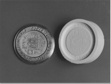
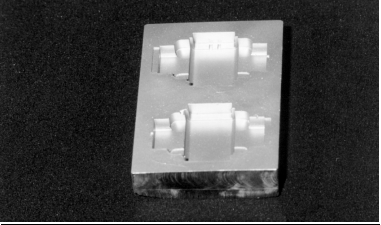
Figure 1. RSP Tooling™ processing steps. An important benefit of RSP Tooling is that it allows molds and dies to be made early in the design cycle for a component. True prototype parts can be manufactured to assess form, fit, and function using the same process planned for production. If the part is qualified, the tooling can be run in production as conventional tooling would. Use of a digital database and RP technology allows design modifications to be easily made. Experimental ProcedureAn alumina-base ceramic (Cotronics 780 [6]) was slurry cast using a silicone rubber master die, or freeze cast using a stereolithography master. After setting up, ceramic patterns were demolded, fired in a kiln, and cooled to room temperature. H13 tool steel was induction melted under a nitrogen atmosphere, superheated about 100°C, and pressure-fed into a bench-scale converging/diverging spray nozzle, designed and constructed in-house. An inert gas atmosphere within the spray apparatus minimized in-flight oxidation of the atomized droplets as they deposited onto the tool pattern at a rate of about 200 kg/h. Gas-to-metal mass flow ratio was approximately 0.5. For tensile property and hardness evaluation, the spray-formed material was sectioned using a wire EDM and surface ground to remove a 0.05 mm thick heat-affected zone. Samples were heat treated in a furnace that was purged with nitrogen. Each sample was coated with BN and placed in a sealed metal foil packet as a precautionary measure to prevent decarburization. Artificially aged samples were soaked for 1 hour at temperatures ranging from 400 to 700°C, and air cooled. Conventionally heat treated H13 was austenitized at 1010°C for 30 min., air quenched, and double tempered (2 hr plus 2 hr) at 538°C. Microhardness was measured at room temperature using a Shimadzu Type M Vickers Hardness Tester by averaging ten microindentation readings. Microstructure of the etched (3% nital) tool steel was evaluated optically using an Olympus Model PME-3 metallograph and an Amray Model 1830 scanning electron microscope. Phase composition was analyzed via energy- dispersive spectroscopy (EDS). The size distribution of overspray powder was analyzed using a Microtrac Full Range Particle Analyzer after powder samples were sieved at 200 µm to remove coarse flakes. Sample density was evaluated by water displacement using Archimedes’ principle and a Mettler balance (Model AE100). A quasi 1-D computer code developed at INEEL was used to evaluate multiphase flow behavior inside the nozzle and free jet regions. The code's basic numerical technique solves the steady- state gas flow field through an adaptive grid, conservative variables approach and treats the droplet phase in a Lagrangian manner with full aerodynamic and energetic coupling between the droplets and transport gas. The liquid metal injection system is coupled to the throat gas dynamics, and effects of heat transfer and wall friction are included. The code also includes a nonequilibrium solidification model that permits droplet undercooling and recalescence. The code was used to map out the temperature and velocity profile of the gas and atomized droplets within the nozzle and free jet regions. Results and DiscussionSpray forming is a robust rapid tooling technology that allows tool steel molds and dies to be produced in a straightforward manner. Examples of die inserts are given in Figure 2. Each was spray formed using a ceramic pattern generated from a RP master.
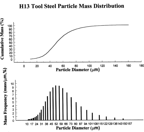
Figure 2. Spray-formed mold inserts. (a) Ceramic pattern and H13 tool steel insert. (b) P20 tool steel insert. Particle and Gas Behavior Particle mass frequency and cumulative mass distribution plots for H13 tool steel sprays are given in Figure 3. The mass median diameter was determined to be 56 µm by interpolation of size corresponding to 50% cumulative mass. The area mean diameter and volume mean diameter were calculated to be 53 µm and 139 µm, respectively. Geometric standard deviation, sd=(d84/d16)½ , is 1.8, where d84 and d16 are particle diameters corresponding to 84% and 16% cumulative mass in Figure 3.
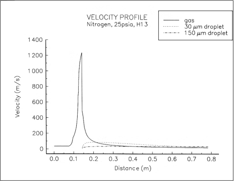
Figure 3. Cumulative mass and mass frequency plots of particles in H13 tool step sprays. Figure 4 gives computational results for the multiphase velocity flow field (Figure 4a), and H13 tool steel solid fraction (Figure 4b), inside the nozzle and free jet regions. Gas velocity increases until reaching the location of the shock front, at which point it precipitously decreases, eventually decaying exponentially outside the nozzle. Small droplets are easily perturbed by the velocity field, accelerating inside the nozzle and decelerating outside. After reaching their terminal velocity, larger droplets (~150 mm) are less perturbed by the flow field due to their greater momentum. It is well known that high particle cooling rates in the spray jet (103-106 K/s) and bulk deposit (1- 100 K/min) are present during spray forming [7]. Most of the particles in the spray have undergone recalescence, resulting in a solid fraction of about 0.75. Calculated solid fraction profiles of small (~30 mm) and large (~150 mm) droplets with distance from the nozzle inlet, are shown in Figure 4b. Spray-Formed Deposits This high heat extraction rate reduces erosion effects at the surface of the tool pattern. This allows relatively soft, castable ceramic pattern materials to be used that would not be satisfactory candidates for conventional metal casting processes. With suitable processing conditions, fine
Figure 4. Calculated particle and gas behavior in nozzle and free jet regions. (a) Velocity profile. (b) Solid fraction. surface detail can be successfully transferred from the pattern to spray-formed mold. Surface roughness at the molding surface is pattern dependent. Slurry-cast commercial ceramics yield a surface roughness of about 1 µm Ra, suitable for many molding applications. Deposition of tool steel onto glass plates has yielded a specular surface finish of about 0.076 µm Ra. At the current state of development, dimensional repeatability of spray-formed molds, starting with a common master, is about ±0.2%. Chemistry The chemistry of H13 tool steel is designed to allow the material to withstand the temperature, pressure, abrasion, and thermal cycling associated with demanding applications such as die casting. It is the most popular die casting alloy worldwide and second most popular tool steel for plastic injection molding. The steel has low carbon content (0.4 wt.%) to promote toughness, medium chromium content (5 wt%) to provide good resistance to high temperature softening, 1 wt% Si to improve high temperature oxidation resistance, and small molybdenum and vanadium additions (about 1%) that form stable carbides to increase resistance to erosive wear [8]. Composition analysis was performed on H13 tool steel before and after spray forming. Results, summarized in Table 1, indicate no significant variation in alloy additions. Table 1. Composition of H13 tool steel
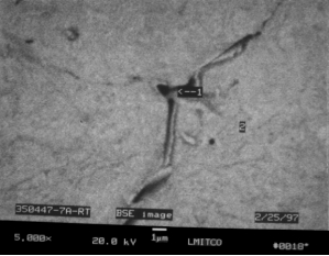
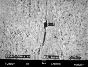
Microstructure The size, shape, type, and distribution of carbides found in H13 tool steel is dictated by the processing method and heat treatment. Normally the commercial steel is machined in the mill annealed condition and heat treated (austenitized/quenched/tempered) prior to use. It is typically austenitized at about 1010°C, quenched in air or oil, and carefully tempered two or three times at 540 to 650°C to obtain the required combination of hardness, thermal fatigue resistance, and toughness. Commercial, forged, ferritic tool steels cannot be precipitation hardened because after electroslag remelting at the steel mill, ingots are cast that cool slowly and form coarse carbides. In contrast, rapid solidification of H13 tool steel causes alloying additions to remain largely in solution and to be more uniformly distributed in the matrix [9-11]. Properties can be tailored by artificial aging or conventional heat treatment. A benefit of artificial aging is that it bypasses the specific volume changes that occur during conventional heat treatment that can lead to tool distortion. These specific volume changes occur as the matrix phase transforms from ferrite to austenite to tempered martensite and must be accounted for in the original mold design. However, they cannot always be reliably predicted. Thin sections in the insert, which may be desirable from a design and production standpoint, are oftentimes not included as the material has a tendency to slump during austenitization or distort during quenching. Tool distortion is not observed during artificial aging of spray-formed tool steels because there is no phase transformation. An optical photomicrograph of spray-formed H13 is shown in Figure 5 together with an SEM image, in backscattered electron (BSE) mode. Energy dispersive spectroscopic (EDS) composition analysis of some features in the photomicrographs is also given. While exact quantitative data is not possible due to sampling volume limitations, results suggest that grain boundaries are particularly rich in V. Intragranular (matrix) regions are homogeneous and rich in Fe. X-ray diffraction analysis indicates that the matrix phase is primarily ferrite (bainite) with very little retained austenite, and that the alloying elements are largely in solution. Discrete intragranular carbides are relatively rare, very small (about 0.1 µm) and predominately vanadium-rich MC carbides. M2C carbides are not observed.
Figure 5. Photomicrographs of as-deposited H13 tool steel. 3% nital etch. (a) Optical photomicrograph. (b) SEM image (BSE mode) near a grain boundary. Table gives EDS composition of numbered features. Figure 6 illustrates the microstructure of spray-formed H13 aged at 500°C for 1 hr. During aging, grain boundaries remain well defined, perhaps coarsening slightly compared to as- deposited H13 (Figure 5). The most prominent change is the appearance of very fine (0.1 mm diameter) vanadium-rich MC carbide precipitates. The precipitates are uniformly distributed throughout the matrix and increase the hardness and wear resistance of the tool steel. Increasing the soak temperature to 700°C results in prominent carbide coarsening, the formation of M7C3 and M6C carbides, and a decrease in hardness. The photomicrographs of Figure 7 illustrate the dramatic change in carbide size. BSE imaging clearly differentiates Mo/Cr-rich carbides from V-rich carbides, shown as light and dark areas, respectively, in Figure 7. EDS analysis of these carbides is also given in Figure 7.
Figure 6. Photomicrographs of spray-formed/aged H13 tool steel. 500°C soak for 1 hr. 3% nital etch. (a) Optical photomicrograph. (b) SEM image (BSE mode) near a grain boundary. Table gives EDS composition of numbered features.
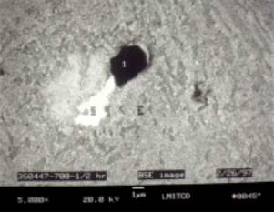
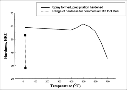
Figure 7. SEM Photomicrograph (BSE mode) of spray-formed/aged H13 tool steel showing adjacent V-rich (dark) and Mo/Cr-rich (light) carbides. 700°C soak for 1/2 hr, 3% nital etch. Table gives EDS composition of numbered features. Material Properties Porosity in spray-formed metals depends on processing conditions. The average as-deposited density of spray-formed H13 was 98-99% of theoretical, as measured by water displacement using Archimedes’ principle. As-deposited hardness was typically about 59 HRC, harder than commercial forged and heat treated material (28 to 53 HRC depending on tempering temperature), and significantly harder than annealed H13 (200 HB). The high hardness is attributable to lattice strain due to quenching stresses and supersaturation. As shown in Figure 8, hardness can be varied over a wide range by artificial aging. 59 HRC as- deposited samples were given isochronal (1 hr) soaks at 50°C increments from 400 to 700°C, air cooled, and evaluated for microhardness. At 400°C, a small decrease in hardness was observed, presumably due to stress relieving. As the soak temperature was further increased, hardness rose to a peak hardness of approximately 62 HRC at 500°C. Higher soak temperature resulted in a drop in hardness as carbide particles coarsened. Peak age hardness in spray-formed H13 tool steel is notably higher than that of commercial hardened material. Normally, commercial H13 dies used in die casting are tempered to about 40 to 45 HRC as a tradeoff since high hardness dies, while desirable for wear resistance, are prone to premature failure via thermal fatigue as the die’s surface is rapidly cycled from 300°C to 700°C during aluminum production runs.
Figure 8. Hardness of artificially aged spray-formed H13 tool steel following one hour soaks at temperature. Hardness range of conventionally heat treated H13 included for comparison. As-deposited spray-formed material was also hardened following the conventional heat treatment cycle used with commercial material. Samples of forged/mill annealed commercial and spray- formed materials were austenitized at 1010°C, air quenched, and double tempered (2 hr plus 2 hr) at (538°C). The microstructure in both cases was found to be tempered martensite with a few spheroidal particles of alloy carbide. Hardness values for both materials were very nearly identical. Table 2 gives the ultimate tensile strength and yield strength of spray-formed, cast, and forged/heat treated H13 tool steel measured at test temperatures of 22 and 550°C. Values for spray formed H13 are given in the as-deposited condition and following artificial aging and conventional heat treatments. Values for the spray-formed material are comparable to those of forged and are considerably higher than those of cast tool steel. The spray-formed material seems to retain its strength somewhat better than forged/heat treated H13 at higher temperatures.
本类最新文章
|
||||||||||||||||||||||||||||||||||||||||||||||||||||||||||||||||||||||||||||||||||||||||||||||||||||||||||||||||||||||||||||||||||||||||||||||||||||||||||||||||||||||||||||||||||