Industrial Robots for Manipulation with Parallel Kinematic Machines
Zden��k Kol��bal
Brno University of Technology, Faculty of Mechanical Engineering, Technicka 2, 616 69 Brno, Czech Republic, e-mail: kolibal@fme.vutbr.cz
Abstract: The presented article analyses structures of kinematic chains in industrial robots, i.e. their positioning and orientation mechanisms with respect to positioning of end - effectors within the workspace of parallel kinematic machine and in its vicinity with the aim to facilitate a selection of appropriate industrial robot for automatic in �C between operational manipulation in the periphery of such a machine or production systems.
Keywords: Industrial robot, kinematic chain, linkage, arrangement, machining centre, parallel kinematic
I INTRODUCTION
With development of control systems and computer technology, the construction of production machines, and machining centres in particular, has witnessed a revival of the so �C called Steward platform positioned in space as a plane suspended evenly in three or six points by means of linear actuators. The same principle forms the basis of the industrial robot with this parallel kinematics of its basic kinematic chain - TRICEPT HP1. written in two columns.
One of the advantages of so designed machining centres is a relative ease of building them into the running work units. Here the use of industrial robots seems to be an appropriate form of in �C between operational manipulations. However, the selection of robots cannot be casual; there has to be an all sided adaptation of the robot to the construction and handling possibilities of parallel kinematic machines, i.e.adaptation in terms of morphology (architecture of kinematic chain, number of degrees of freedom), in terms of purpose (selection of appropriate end effectors, if possible automatically replaceable) and in terms of control [3].
If, however, the machining centre is not equipped with another manipulation peripheral device, as can be seen e.g. in Fig. 1, the industrial robot has to directly encompass the work space of the serviced machining centre and a flow of material (semi - products and work �C pieces) is accomplished directly by this industrial robot.
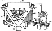
Figure 1a
Machining centre of company INGERSOLL
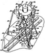
Figure 1b Machining centre of company Kearney & Trecker
In the case of periphery from Fig. 1, it is evident that a pertinent industrial robot to be used for further manipulation is not significantly limited in terms of mainly its morphology selection (kinematic structure); therefore these cases are not a subject of the present work.
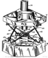
A completely different is the case when a direct robotic manipulation is required for the machining centre with parallel kinematic, which is designed in terms of current trends, i.e. the components and mechanisms of the centre virtually encompass its workspace (see Fig. 2).
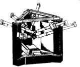
Figure 2a Machining centre of FhI Chemnitz
Current machining centres with parallel kinematics (see Fig. 2) can, in terms of industrial robot direct serviceability, rank among production machines with space �C limited serviceability; therefore this should betaken into account for the selection of industrial robots.
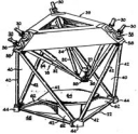
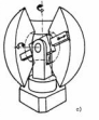
Figure 2b Machining centre of company GIDDING & LEWIS
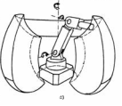
Figure 2cMachining centre of company INGERSOLL
II BASIC AND DERIVED TYPES OF INDUSTRIAL ROBOTS
As stated in most of the existing publications, basic types of industrial robots can be those described in Fig. 3:
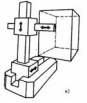
Figure 3aCartesian type (K) with linkage of kinematic pairs TTT
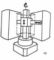
Figure 3bCylindrical type (C) with linkage of kinematic pairs RTT
Figure 3cSpherical type (S) with linkage of kinematic pairs RRT
Figure 3d Anthropomorphous (angular, torus) type (A)with linkage of kinematic pairs RRR
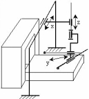
Further practical use and monitoring of robots development revealed the occurrence of industrial robots with a structure of kinematic pairs linkage different from that corresponding to basic workspaces as e.g. with the industrial robot "UM-160" or GE- ROBO; their structure ZKR can be expressed, as seen in Fig. 4, by a kinematic pairs linkage TRR. Practice therefore proved theory that sets for n - degrees of freedom the number of possible linkages of kinematic pairs T and
R: m = 2n (1)
where n is natural number.
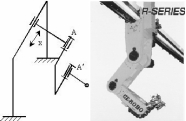
Figure 4 Scheme of basic kinematic chain of industrial robots UM-160 and GE-ROBO
For the practical and commonly used number of degrees of freedom n = 3, the basic so analysed number of linkages is extended in total up to
m =23 = 8 groups: TTT, RTT, TRT, TTR, RRT, RTR, TRR, RRR.
This set of linkages has already encompassed the above - mentioned structure of robot from Fig. 4; it is therefore possible to refer to a derived structure of the basic kinematic chain of this robot by virtue of its kinematic pairs. Each of kinematic pairs, employed in the basic kinematic chain, can however be further located in one of the three different directions given by the Cartesian system of coordinates x,y,z as follows:
translation (T) in the direction of coordinates X,Y,Z,
rotation (R) around these coordinates A,B,C,
wherefrom within the respective linkages, further possible different arrangements originate, e.g..Tx,Ty,Tz in contrast to Tx,Tz,Ty, etc.
The Institute of Production Machines, Systems and Robotics of FME BUT has been paying a long-time attention to the study of arrangements of positioning mechanisms. The use of the so �C called combinatorial algorithms [1], [2], [5], their mathematical expression and morphological analysis with constructional evaluation enabled us to assess the arrangements in all eight linkages and to state that - out of 165 theoretically possible arrangements 47 various non �C isomorphous solutions can be used for constructional practice. However, some of the workspaces thus obtain the so �C called ��shell�� character. So far 13 arrangements have been used in practice as can be seen from the following evaluation:
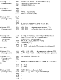
In total 3+4+5+6+6+10+7+6 = 47
arrangements, out of these 8 ��shell��.
A performed theoretical analysis enables us to classify various types of IRaM within a set of possible types(basic and derived) and also provides us with premises for building up new constructions, e.g. the following designs of robot configurations to service machining centres with parallel kinematics.
III SELECTION AND DEVELOPMENT OF INDUSTRIAL ROBOTS SUITABLE TO SERVICE MACHINING CENTRES WITH PARALLEL KINEMATICS
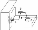
From configuration structures of basic types of industrial robots in Fig. 3 it is evident that the type ��A�� in particular is not suitable to service machining centres in Fig. 2. Questionable is also the above - described type ��K��(linkage TTT, arrangement xszsy), whose locomotion in the basic direction (x s) is accomplished on the base that will undoubtedly form an inconvenient barrier in front of the machining centre. The above described types ��K��, ��C�� (linkage RTT, arrangement CZX) and also type ��S�� (linkage RRT, arrangement CAY) seem to be more convenient for the required servicing because they have �C as an end member of the basic kinematic chain �C a protruding arm and types ��K�� and ��C�� (linkage RTT, arrangement CZX) even have a horizontal arm that can appropriately encompass the workspace of the machining centre [4]. The most suitable solution to meet these requirements is a portal design in the linkage of type ��K�� (TTT) with a subsequent vertical member in a sliding shoe design (z) and a horizontal member (y) at the end of the basic kinematic chain. This is therefore the arrangement XYZ but in a modified form xportalzy (see Fig. 5).
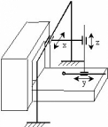
Figure 5a with single horizontal arm
Figure 5b with rotary dual arm to accelerate a manipulation cycle
The locomotion of the horizontal arm of the industrial robot is however linked with certain problems related to its possible further rotation. The locomotion of end effectors of the basic kinematic chain, as seen in Fig. 5, is actually performed in front of and behind the robot base so that a complete rotation of the machining centre is in fact impossible. A possible dual arm (Fig. 5b) can form an angle of maximum 90��. A more suitable solution would be if the robot could drive a little forward from the machining centre or if it were not situated in the middle of the machining centre.
For these reasons, on the basis of morphological analysis, it will be presumably necessary to develop further modified types of industrial robots. One of the possibilities could be the use of shell structure with arrangement CAX (CBY) as seen in Fig. 6a, which could be convenient for machining centres with an external peripheral device (feeder), or a suspension modification of type SCARA with arrangement AAX (BBY), as seen in Fig. 6b, enabling a further sufficiently long second member of the basic kinematic chain to rotate by 180�� outside the machining centre.
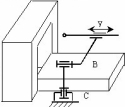
Figure 6a arrangement CAX (CBY)
Figure 6b arrangement AAX (BBY)
Conclusion
The presented selection and proposals for development of robotic systems to service machining centres with parallel kinematics are based on a long �C time research of morphology of mobile robotic systems and industrial robots, respecting thus a relatively difficult access to workspace of these machining centres. A set of proposed types is far from being complete; it rather strives to make a contribution to the specification of this problem and to the search for possible solutions.
References
[1]B��lohoubek, P., Kol��bal, Z.: The knowledge from the Research in the Field of Robotics at UT Brno, Czech Republic. In: Automazione/Automation 1993, BIAS, Milano, Italy, November 23-25, 1993, pp. 723-726
[2]Kol��bal,Z.: The Theory of the Structures of Basic Kinematic Chains in Industrial Robots and this Effect on their Practical Application. In: 8th International Workshop on Robotics in Alpe- Adria-Danube Region RAAD 1999, Edited by Franz Freyberger and G��nter Schmidt, M��nchen, June 17-19, 1999, Technische Universität M��nchen, Germany, 1999, ISBN 3-00-004482-5, pp. 127-132
[3]Knofl��ček, R.- Marek, J.: Obr��b��c�� centra a průmyslov�� roboty s paraleln�� kinematickou strukturou. In: Stroj��rensk�� výroba, ročn��k 45, 1997, č.1-2,ISBN 0039-24567, pp. 9-11
[4]Kol��bal, Z.- B��lohoubek, P.: Die Analyse der geeigneten Gestaltung des Industrie-roboters f��r die Handhabung bei den Bearbeitungszentren mit paralleler Kinematik. In:. Tagungsband des 2.Chemnitzer Parallelkinematik-Seminar„Arbeits-genauigkeit von Parallelkinematiken��, 12/13. April 2000, Verlag
Wissenschaftliche Scripten, Zwickau, Germany, ISBN: 3- 928921-54-1, pp. 441-455
[5]Kol��bal, Z.: The theory of basic kinematic chain structures and its effect on their application in the design of industrial robot positioning mechanisms. CERM Akademick�� nakladatelstv��, s.r.o. Brno, 2001, ISBN 80-7204-196- 7, p. 71