ACI STRUCTURAL JOURNAL TECHNICAL PAPER Title no. 107-S61
Creep Effects in Plain and Fiber-Reinforced Polymer-Strengthened Reinforced Concrete Beams
by M. M. Reda Taha, M. J. Masia, K.-K. Choi, P. L. Shrive, and N. G. Shrive
The long-term deflection behavior of two reinforced concrete (RC) beams with similar dimensions and material properties was monitored. One beam was externally strengthened with fiberreinforced polymer (FRP) strips, whereas the other was used as a control specimen. Both beams have been subjected to sustained loading for over 6-1/2 years. The objective of the experiments was to assess the significance of creep in the epoxy adhesive and whether such creep might allow the FRP strips to unload over time. Slip movements at the ends of the FRP strips were also monitored.
The experimental deflections have been compared to deflection predictions using ACI 209R-92 and CEB-FIP MC 90. The creep deformations of the FRP-strengthened beam are not as predicted from the control beam. Two analytical approaches are used: a step-by-step in-time analysis and finite element (FE) modeling. Both techniques demonstrate that creep of the adhesive layer can account for the differences observed between the predicted and actual behaviors of the beams.
Keywords: creep; deflection; epoxy adhesive; fiber-reinforced polymer(FRP); reinforced concrete.
INTRODUCTION
In recent years there has been much research on the use of fiber-reinforced polymers (FRPs) to strengthen existing concrete structures. One popular application, used widely in practice, is to bond FRP strips externally to the tension face of reinforced concrete (RC) beams to increase flexural capacity.
The FRP strips are typically bonded directly to the prepared concrete surface using an epoxy adhesive. The strips may be anchored mechanically near their ends or supported by additional shear reinforcement, usually in the form of U-shaped FRP sheets. If the beam is subsequently loaded with sustained loads, creep in the epoxy adhesive could take place and would allow the FRP strips to unload, leaving them ineffective against the sustained load. Similarly, if the strips are prestressed as recently recommended by some researchers (for example, Ye et al.1), creep in the epoxy may relieve some of the initial force. Hence, although the FRP strips can still assist in supporting additional live load, the increased sustained loads may exceed the capacity of what could effectively become the original unstrengthened beam.
Research into the time-dependent behavior (creep and shrinkage) of concrete beams strengthened with externally bonded FRPs is scarce. Analytical models were verified against limited experimental observations of RC2 and timber3 beams externally reinforced with FRP strips. Similar approaches were used for a composite glass fiber-reinforced polymer (GFRP) box girder with concrete in the compression flange and a carbon fiber-reinforced polymer (CFRP) strip bonded to the tension face.4 In all of the aforementioned models, however, the effect of creep in the adhesive layer bonding the FRP to the tension face of the beams was neglected. That is, perfect bond and strain compatibility was assumed between the substrate and the FRP. Recent experiments by Choi et al.5 demonstrated that significant creep under shear stresses occurs in the epoxy at the concrete-FRP interfaces when loading is applied within 7 days of epoxy application.
Herein, the results of an experimental investigation and accompanying analytical predictions of immediate and timedependent beam deflections are described. The construction of the RC beams and the experimental program for observing their time-dependent deflection are presented. The measured deflections are compared to deflection predictions using the ACI and CEB-FIP methods implemented according to the recommendations of Hall and Ghali.6
The long-term deflection data show that the timedependent (creep) deformation of the CFRP-strengthened beam is a larger proportion of its immediate deformation than the same deformation ratio for the unstrengthened beam. The creep of the beam with the FRP strips could not be predicted from the creep measured on the plain beam when creep of concrete alone was considered. Because CFRPs have not been observed to creep at the stress levels generated,7,8 the additional creep may have occurred in the epoxy adhesive bonding the FRP strips to the concrete.
The creep mechanism is expected to be a simple flow of the epoxy under the shear stress,5 which develops to create tension in the FRP strip. While models exist for predicting long-term deformation of RC beams strengthened with FRP (for example, Charkas et al.9), these models do not account explicitly for creep of epoxy adhesives. Herein, we use two different approaches to determine if creep in the epoxy can account for the different behaviors observed in the beams: a step-by-step in-time analysis allowing incremental creep of concrete and epoxy in each time step and enforcing equilibrium at the end of the time step, and finite element (FE) modeling with shear flow allowed in the epoxy adhesive layer.
RESEARCH SIGNIFICANCE
The potential effects of creep on RC beams strengthened with externally applied FRP strips are considered. It was thought that creep in the epoxy resin might relieve stress in the FRP, making the FRP less effective from a serviceability point of view under sustained loads. Thus, FRP strips used to strengthen a beam, which was then subject to increased sustained load, might end up with the extra sustained load being carried by the original concrete and steel reinforcement, not the FRP. The experimental and analytical work performed revealed that the situation is more complex. Nevertheless, creep deflections are greater than predicted from the creep of concrete alone, indicating contributions from creep of the epoxy. The reported experimental program was designed to identify the existence of epoxy creep rather than replicate a practical retrofit scenario. The results highlight the potential for epoxy creep to affect the long-term performance of FRP retrofits in practice.
EXPERIMENTAL PROGRAM
Test specimens and materials
Two similar RC beams were cast from the same concrete batch (Fig. 1). Each beam was 3500 mm (137.8 in.) long, 280 mm (11.02 in.) wide, and 180 mm (7.09 in.) high, reinforced with four longitudinal bars (Canadian 10M-11.3 mm [0.445 in.] diameter, 100 mm2 [0.155 in.2] area) at an effective depth of 135 mm (5.31 in.) from the top surface of the beam. Seven 10M stirrups were spaced uniformly in each shear span of each beam. The 28-day compressive strength of the concrete, as determined from 100 mm (4 in.) diameter, 200 mm (8 in.) high cylinders―cast from the same batch of concrete as the test beams―was 34.3 ± 2.3 MPa (4900 ± 328 psi).
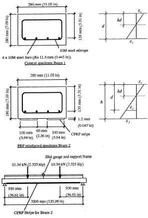
Fig. 1―Test specimens, test setup, and strain distribution.
The two beams were cast together and stored―fully supported―for 10 months before the CFRP strips and GFRP wraps were applied. One beam (Beam 1) was designated as a control ・specimen. Two CFRP strips were bonded to the tension face of the second beam (Beam 2) using an epoxy adhesive. The strips are 100 mm (3.94 in.) wide, 1.2 mm (0.047 in.) thick, and 2970 mm (116.9 in.) long. Over the shear spans at each end of Beam 2, GFRP sheets were wrapped in a U-shape to cover the two side faces and the tension face of the beam. The CFRP strips are unidirectional with the fibers aligned along the length of the beam. The strips have a modulus of elasticity of 165 GPa (23,571 ksi) and a tensile strength of 2800 MPa (400 ksi) in the direction of the fibers (manufacturer’s data).
Test setup and procedure
The beams were simply supported (pin-roller) over a span of 3200 mm (125.98 in.) (Fig. 1). The midspan deflection due to self-weight was recorded using a dial gauge (least count 0.01 mm [0.000394 in.]) mounted on a lightweight steel frame over the 3200 mm (125.98 in.) span. For Beam 2, electronic spring gauges were mounted on the concrete adjacent to each end of one of the CFRP strips. The deflected tip of the spring gauge was carefully positioned to touch the exposed end of the CFRP strip. These gauges were designed to record the longitudinal slip of the ends of the CFRP strip relative to the concrete to which the strip is bonded. Each beam was then loaded in four-point bending by applying two-point loads (each 10.34 kN [2.325 kips]) at a distance of 930 mm (36.61 in.) from each support. This level of loading was designed to push both beams into their working range. For Beam 1, the load was expected to result in significant cracking of concrete in the tensile zone, but stresses in the concrete in compression and steel in tension would remain elastic. In Beam 2, the load was expected to cause far less damage but still result in significant deflections over the long term. The loads were provided by hanging concrete blocks on load hangers bearing on the upper surface of each beam. The loads were transferred to the beams by gradually lowering the blocks onto the beams using hydraulic jacks. The hydraulic jacks were then removed. The midspan deflection of each beam relative to the self-weight value as well as the relative slip movements for the CFRP strip were recorded immediately after loading and at regular intervals thereafter. Data were recorded several times during the first 24 hours of loading, daily for the first month after loading, increasing to every 3 days, weekly, biweekly and, finally, greater intervals. The loaded beams are located in the airconditioned basement level of a laboratory building where the average temperature is expected to remain relatively constant with time.
Experimental results and discussion
Upon loading, the immediate midspan deflections of the beams relative to the measured self-weight deflections were 10.01 and 3.76 mm (0.394 and 0.148 in.) for the control and CFRP-strengthened beams, respectively. Numerous flexural cracks were observed extending from the tension face of the control beam, predominantly over the region of constant bending moment between the point loads. No flexural cracks were observed in Beam 2 at first loading. Such cracking would be hard to see unless significantly wide, due to the existence of the FRP strips. This is because the tensile strain in the FRP will be constant in the constant-moment section. If there were a few wide flexural cracks, the strain, and thus the stress, in the FRP would dramatically vary between the FRP still bonded to the concrete and the FRP stretching across such cracks. Equilibrium of the FRP strip has to be maintained; therefore, rapid and large variations in force in the strip are not possible, as there is no mechanism to accommodate such stress variation. Hence, the concrete in the constant-moment section has to crack with a large number of very thin cracks so that the strain in the FRP remains constant. Several months after loading, a thin flexural crack could be seen extending from the tension face of Beam 2 close to the beam midspan. The CFRP strips significantly increased the cracking moment capacity of Beam 2. Although not tested, the additional FRP reinforcement was also expected to increase the ultimate moment capacity of the beam.
The long-term midspan deflections (total deflection minus the initial deflection) of both beams are shown in Fig. 2, plotted versus time after loading up to 2470 days of loading. The relative slip movements versus time at each end of one of the CFRP strips bonded to Beam 2 are shown in Fig. 3. Several observations can be made:
1. The long-term deflection of Beam 2 is significantly less than that of Beam 1. Long-term deflection due to concrete creep is a function of the immediate deflection, which depends on cross-sectional stiffness and cracking status. Beam 1 cracked much sooner than Beam 2.
2. The long-term deflection of Beam 2 constitutes a larger proportion of its immediate deflection compared with Beam 1. Plevris and Triantafillou2 observed a similar response in beams externally reinforced with FRP strips compared to their control specimen (no FRP).
3. The midspan deflection for Beam 2 does not appear to be “catching” that of Beam 1. That is, at first appearance, there is no indication that the CFRP reinforcement is unloading, thereby becoming ineffective against the sustained load.
4. The rate of increase of deflection changes with time. This is particularly evident when compared to the smooth curves of predicted long-term deflections discussed and presented in the following sections (Fig. 2, 4, and 5). Similar trends occur for both beams. The periods of reduced rate of increase of deflection coincide with the summer months and those of increased creep coincide with the winter months. In the calculation of creep coefficient using CEB-FIP,10 the creep coefficient reduces as the relative humidity increases, implying a reduced rate of creep during periods of higher relative humidity. The relative humidity was not recordedduring the current tests. However, relative humidity was recorded during creep tests by Hall and Ghali,6 conducted in the same laboratory as these tests. Their results showed relative humidity varying between 5 and 50%, with a summertime average of approximately 35% and a wintertime average of approximately 10%. The observed changes in creep rate are thus believed to be seasonal and depend on changes in relative humidity.
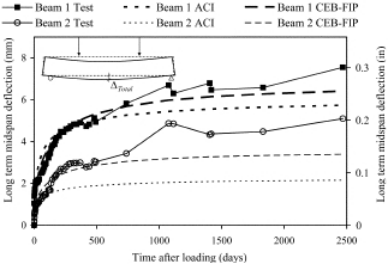
Fig. 2―Experimentally measured long-term midspan deflection versus time after loading (recorded up to 2470 days) and as predicted for both beams using CEB-FIP10 and ACI11 models.
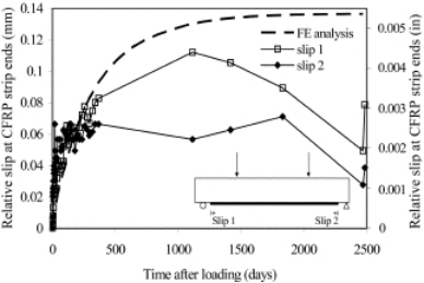
Fig. 3―Relative slip versus time at each end of one CFRP strip (Beam 2) as measured and as predicted using FE model.
5. Some relative slip occurred between the concrete and CFRP strip at the strip ends soon after loading, as shown in Fig. 3. Since then, the movement at one end of the strip has essentially stabilized and only a relatively small gradual movement has occurred at the other end. The significant scatter in the slip readings, particularly late in the data record, is thought to result from temperature variations in the strain gauges between dates of reading (the beams are beside an air-conditioning outlet) and repeated reconnection/disconnection of the measurement instrumentation for these gauges. The maximum relative slip at the ends of the gauged CFRP strip within 2470 days was in the order of 0.17 mm (0.0067 in.)―an average of approximately 60 microstrain over the length of the strip―which implies an average loss of tensile stress of approximately 9 MPa (1285.7 psi) in the strips, and translates to an average loss of tensile force of approximately 1 kN (0.225 kips) per strip. Fifty percent of this movement occurred in the first 3 weeks after loading. This observation agrees with those reported by Choi et al.,confirming that the majority of epoxy creep occurs in a relatively early time period.
ANALYTICAL PREDICTION OF DEFLECTIONS
Analytical predictions of the beam deflections were made in an attempt to identify any features of the behavior not obvious from the experimental results alone. First, the simplified procedures of CEB-FIP10 and ACI11 were used. These procedures focus on accurate modeling of concrete creep―and thus deflection―without considering the effect of creep of epoxy. A step-by-step in-time analysis and an FE model were therefore developed to examine the combined effect of creep of the concrete and of the epoxy on the longterm deflection.
Analytical prediction of deflections using CEB-FIP and ACI
Approaches based on the CEB-FIP Model Code 1990 and the ACI Committee 209 recommendations11 were used by Hall and Ghali6 with the former being shown to achieve good agreement with experimental results for concrete beams reinforced with steel bars and concrete beams with GFRP bars in place of the steel bars. Both approaches aim at estimating long-term deflections due to the effects of creep and shrinkage in the concrete. The methodologies are described in detail by Hall and Ghali6 and Masia et al.
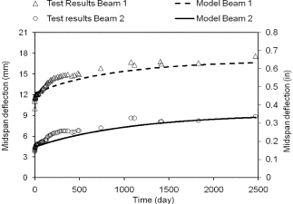
Fig. 4―Deflections predicted by step-by-step in time model versus experimentally measured deflections for Beam 1 (reinforced with steel only), including effect of concrete creep and tension stiffening of concrete (î = 0.9) and Beam 2 (reinforced with steel and FRP), including effects of concrete creep, tension stiffening of concrete ( ), and stress relaxation of FRP-epoxy composite (
 and
and days).
Results of analytical deflection predictions using CEB-FIP10 and ACI11
The CEB-FIP10 approach was first used to predict the immediate midspan deflections of both beams. The model predictions were calibrated against the experimental results by adjusting the cracking moment for each beam. These cracking moments are best-fit values representing the observed deflections (immediate midspan deflection measured relative to the self-weight deflection) in the beams and not derived from the cracking strength of concrete. The cracking moments were determined in this way because the tensile strength and design shrinkage strain of the concrete, required for direct estimation of the cracking moments, were not measured in the experimental program. The cracking moments determined were used later in calculating the longterm midspan deflections for the two beams. The cracking moment capacities obtained from the calibration were 4.52 kN.m (40.08 kips.in.) and 9.12 kN.m (80.87 kips.in.), respectively, for Beams 1 and 2. The large difference highlights the strengthening effects of the CFRP strips. The difference is also consistent with the observation of minor cracking for Beam 2, whereas significant cracking was observed in Beam 1 (note that the maximum bending moment due to beam self-weight and applied sustained loading is 11.13 kN.m [98.69 kips.in.]).
The long-term midspan deflections of each of the beams were then predicted for all times after loading, at which experimental readings were recorded. The ultimate creep coefficients for concrete were adjusted to provide a leastsquares best fit between the predicted and experimental deflection values for the Control Beam 1. The same ultimate creep coefficients were then used to predict the long-term deflections for Beam 2, assuming no creep in the adhesive bonding of the CFRP to the concrete. The use of the ultimate creep coefficients derived from Beam 1 to analyze Beam 2 is a valid assumption, as both beams were cast from the same concrete batch at the same time and loaded at the same environment. Deflections due to shrinkage strains in the concrete were neglected. The two beams were loaded approximately 300 days after casting, after which timeapproximately 90% of the total shrinkage strain was achieved.6 Further, as the second beam was not “strengthened” until 285 days, the drying creep of the two beams was assumed to be the same.
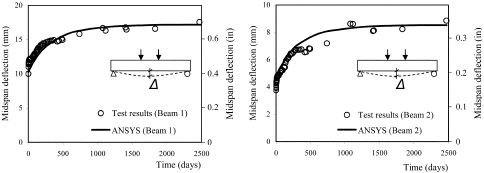
Fig. 5―Long-term deflections at midspan of beams using FE method: (a) Beam 1, considering creep of concrete; and (b) Beam 2, considering combined effect of creep of concrete and creep of epoxy adhesive.
