|
|
|
| �ס�ҳ | ��е��ҵ��� | ���ӵ�����ҵ��� | �������ҵ��� | ��ľ���̱�ҵ��� | �Ӿ������ҵ��� | �������� | �Ŀ����� | �������� | �������� | ������� |
���������ڵ�λ�ã���ҳ >>�������� >> �������� |
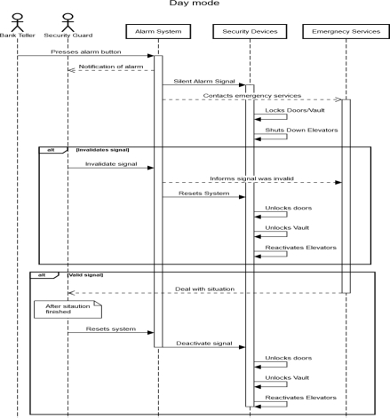
Figure 5 �C Bank security system class diagram [1,2]. 4.5 Sequence Diagram4.5.1 Day ModeIn Day Mode the alarm system can be activated by either a bank teller using the panic button under their till, or by a security guard. The alarm system will then enter Emergency state, during which the doors and vault will be locked, to prevent more customers from entering, and to prevent the robbers from accessing most of the money. The elevators will also be shut down to prevent customers or employees on other floors from entering a dangerous area. The system will also alert the security guards and emergency services of the incident. The security guards can invalidate the signal in the case of a false alarm. The security guards can also deactivate the door locks to allow the emergency services to enter, or can reset the system in the case of a false alarm.
Figure 6 �C Day mode sequence diagram showcasing the process after panic button has been pressed [2,5,7]. 4.5.2 Night Mode
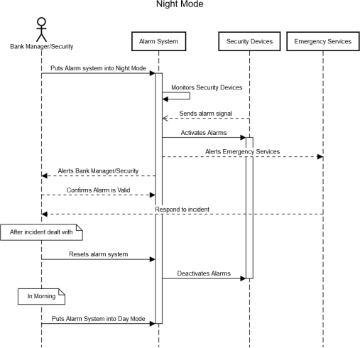
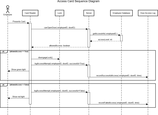
Figure 7 �C Night mode sequence diagram showing the systems processes for a break in [2,5,7]. 4.5.3 Keycard Door AccessAccess management for employees to restricted areas is provided using personal keycards and card readers on the doors. When an employee scans their card, the reader will send a request to the main server running the system, which will then consult the employee database to see if the employee should be allowed access to that area. The server will then send the response to the card reader and log the access attempt (either successful or failed) in the door access logs. When the card reader receives the response from the server it will either unlock the door and display a green light, or not unlock the door and show a red light.
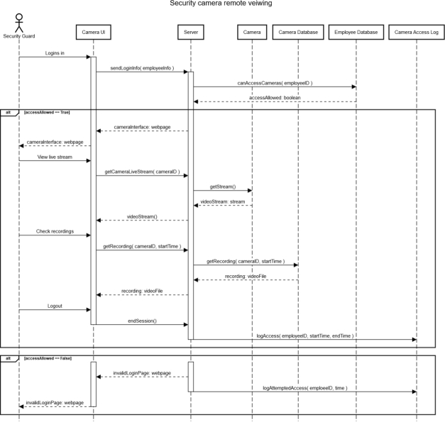
Figure 8 �C Sequence diagram for keycard authorization access through a locked door [2,5,7]. 4.5.4 Camera Access
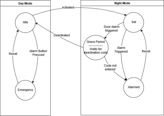
Figure 9 �C Sequence diagram for camera live feed access [2,5,7]. 4.6 State DiagramThere are 2 modes the system can operate in; Day Mode, and Night Mode. Each with 2 main states. In Day Mode the system will normally be in Idle state, where none of the sensors are active, but keycards are still logged and cameras record. It can be changed to emergency state by pressing one of the panic buttons. In this state the alarm system will lock the doors and the vault, deactivate the elevators, and contact the emergency services. It can be set back into Idle state by the manager or a security guard resetting the system.
Figure 10 �C Bank security system state diagram for all four system states: Idle, Emergency, Set and Alarm [6]. 4.7 Activity DiagramThe Activity Diagram is a form of behavioural model that displays the dynamic behaviour of the Bank Security system as it is executing. It shows the system processing that occurs when the security system reacts to an event from the environment, i.e. the pressing of a panic button which is a state transition action. The diagram shows the sequence of processes taken after the panic button has been pressed and the system outputs produced due to that action. This diagram benefits the requirement analysis as it shows the end-to-end processing of a system [8].
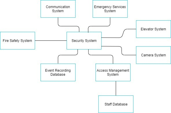
Figure 11 �C Activity diagram showing the systems process that occur after the panic button has been pressed. 4.8 Context Diagram The Context Diagram provides the highest level view of the Bank Security system, displaying the system as a whole and shows its interactions with external systems that lie outside of its boundaries. It is a form of data flow diagram that outlines the system and the other systems which it communicates with. Before a process model can be produced the project scope must be defined. This determines the specific objectives, deliverables, boundaries and tasks of the system and how it interacts with other systems in the Bank. A context diagram is a graphical representation of a project��s scope [2,7].
Figure 12 �C Bank security system context diagram displaying other systems in contact with itself. 4.9 Data Flow Diagrams 4.9.1 Security System
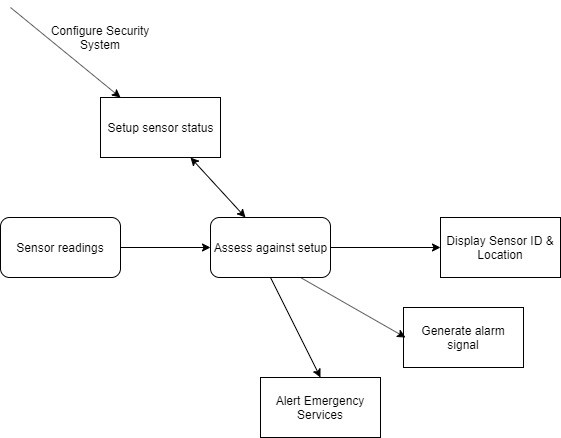
Figure 13 �C Data Flow diagram for the security system through the control panel and system [9]. 4.9.2 Sensor Monitoring System
Figure 14 �C More in-dept data flow diagram for the sensor monitoring aspect of the bank security system [9]. 5 Management Charts 5.1 List of Personel with Skills To complete this project, each team member has been given a specific role. Each member��s role has the appropriate skill set which will enable us to complete all the mentioned documentation. The team will consist of: �� Team Leader (Darragh Glavin - 16189183) is responsible for the system overview, management chart, staff skills and work allocations, Gantt chart and Network (Activity). �� Quality Manager (Christophe Hirt - 19099096) will be involved in all the system requirement documentation, reviewing the system analysis and architecture, and risk management. �� Project Owner (Leonard Anatole - 19150059) will also be involved with the system requirement documentation, specifying exactly what the customer (Bank) is looking for with this product. �� Security Specialist (Loic Talon - 19144865) who has expertise knowledge of security systems, sensors and protocols. He will be involved in the system requirement stages and the risk management stage. �� System Architect (Colin O��Sullivan - 16190963) and Software Architect (Lorcan Williamson - 16160703) will be working on the System Analysis/model architecture and any Use, Class, Interaction, state and activity diagrams. Weekly team meetings were scheduled on Tuesdays to maintain a constant work rate throughout the term discuss the project and the progress on tasks. Each team member presented their work and received feedback and corrections to be made. 5.2
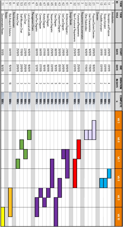
Figure 15 �C Gantt chart showing the project sections, working duration and due date. 5.3 Staff Allocation
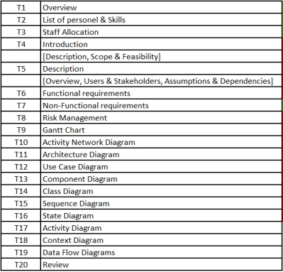
Figure 16 �C Task list and abbreviations.
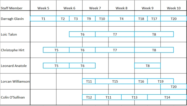
Figure 17 �C Staff allocation chart for project. 5.4 Activity Network Diagram
Figure 18 �C Activity network diagram for task completion order, milestones and critical path. 6 Risk Assessment & Proposed Solutions 6.1 Risk during the development - Respect of the delay Risk : If a developer is sick or can��t handle his/her job, the deadline of the project, given by the client, won��t be respected. Solution : To have a developer ready in case of a problem with the other developer. No single point of failure, ie. anyone should be able to do any job. - Data crash Risk : The server can��t handle all the information they will obtain from the database. Solution : To check what is going to be in the database before finding the server to carry the data. 6.2 Risk of the system - Locking the emergency exits Risk : This allows not to have more people coming into the bank but it locks the public and employees inside with the robber(s). Solution : Police get a special pass to open the door from the outside or Bank staff can re-open the door with an identification code or their employee��s card, to open the locked doors. - Having people trapped in the elevator during the robbery Risk : During day-robbery, people would be trapped in the elevator if switched off to control foot traffic flow. Solution :The system should detect if there is someone in the elevator. If someone is detected, the elevator will have to go on the last floor to let the people get out of it but without facing the robber(s) at the first floor. The elevator cannot be active during an emergency situation as it would place more people in danger and allow ay potential robbers access to other levels. - Staff access cards stolen for entry to locked areas Risk : The staff card provide access to locked areas, if thieves take them, they can open any door. Solution : Many possibilities can counter that, first, critical paths can remain locked (vault/offices/data storage) to anybody because they aren��t block an emergency exit route. Also, remote access to open the doors can be given, a security guard could unlock certain doors if required and safe to do so. - Having more reliability to activate the emergency state Risk : If a bank teller can��t activate the emergency state, there needs to be someone/something else to activate it. Solution : Depending on the size of the bank, different solutions could be applied. First, security cameras should constantly watch the bank, then if it is an ��important�� bank a dedicated security staff should keep an eye on the cameras transmission and could activate an emergency state. In ��less important�� bank buildings, a recognition software should analyze the cameras and if any troubles are detected ( mask/guns/strange behavior), the software would contact an external security agency to manually check the camera records and then they could activate the emergency state. - Accidental activation of the emergency state Risk : Since the ��panic button�� should be accessed easily and the fastest way possible, the bank teller could press it accidentally. Solution : A security guard should be able to deactivate the emergency procedure, meaning that the procedure would always keep going ( because it needs to be efficient ). The possibility of deactivation would have a timer (around 30 seconds) to avoid any deactivation from the robber(s). - Database and system hack Risk : A cyber attack can disable the security system, to steal the bank data with the access to the cameras�� recording, and employees�� and customers�� information or even to create a fake identification in the employee identification data. The Software cannot be isolated from external use because it needs to reach/contact the emergency staff. Solution : Having the most reliable security protocol against cyber attack and to encrypt the data. 6.3 Aftermarket Risk of the system - Maintenance and after-sales service Risk : The main risk after the sale of the system is if there is a problem with the system (a crash, in the worst case a hack, ect). Solution : Keep testing the software with simulation and provide good maintenance services to the clients after they buy the product. 7 Conclusion: This project looked at the production of software documentation required for a Bank Security system. These documents provide the foundations for a bank security system software development process should one be required. Functional and Non-Functional requirements were produced from discussions between the team and the customers representative, the product owner. From these an overview of the whole system including its scope and feasibility, user and stakeholders, and numerous UML diagrams and complementary diagrams which are not formally classed as UML but provide important analysis of the requirements documentation to ensure an equal understanding of the security system between both parties. This resulted in a reliable, robust and efficient security system��s documentation for a bank was produced, that aimed to guarantee asset protection but optimise for customer and staff safety with features such as a state invalidation protocol over a validation version which would cause a delay in response time. Management documentation was utilised to organise the spreading of tasks amongst team members, the flow of tasks from completion of one to commencement of another, members that should be working together on a task, and setting due dates to ensure a constant work rate to maintain the project timeline. Risk management was outlined to understand any potential problems that can be foreseen and how these have been accounted for in the documentation via solutions References: [1] K. Fakhroutdinov, "UML class diagrams examples - Abstract Factory Design Pattern, Li- brary Management, Online Shopping, Hospital, Digital Imaging in Medicine, An- droid.", Uml-diagrams.org, 2019. [Online]. Available: https://www.uml-diagrams.org/class- diagrams-examples.html. [Accessed: 01- Nov- 2019] [2] I. Sommerville, Software Engineering, 10th ed. 2015. [3] "Component Diagrams - See Examples, Learn What They Are", Smartdraw.com, 2019. [Online]. Available: https://www.smartdraw.com/component-diagram/. [Accessed: 01- Nov- 2019] [4] "Architecture Diagram Overview", Edrawsoft.com, 2019. [Online]. Available: https://www.edrawsoft.com/architecture-diagram.php. [Accessed: 01- Nov- 2019] [5] "OMG unified modelling language (OMG UML), Superstructure, V2.4.1, p. 507", Omg.org, 2019. [Online]. Available: https://www.omg.org/spec/UML/2.4.1/Superstructure/PDF. [Ac- cessed: 01- Nov- 2019] [6] D. Harel, "Statecharts: a visual formalism for complex systems", Science of Computer Pro- gramming, vol. 8, no. 3, pp. 231-274, 1987. [7] H. O.Alanazi, "On the Module of Internet Banking System", Pdfs.semanticscholar.org, 2010. [Online]. Available: https://pdfs.seman- ticscholar.org/6be2/352c5dc619626c342eb419ca7d337b8c0877.pdf. [Accessed: 07- Nov- 2019] [8] "Unified Modeling Language (UML) | Activity Diagrams - GeeksforGeeks", Geeksfor- Geeks, 2019. [Online]. Available: https://www.geeksforgeeks.org/unified-modeling-lan- guage-uml-activity-diagrams/. [Accessed: 04- Nov- 2019] [9] Lucidchart.com, 2019. [Online]. Available: https://www.lucidchart.com/pages/data-flow- diagram. [Accessed: 10- Nov- 2019] ,Table of Contents 2.1 Overview 4 2.2 Users of proposed system 7 2.4 Assumptions & Dependencies 9 3.1 Functional 10 3.1.1 Day system analysis 10 3.1.2 Night system analysis 11 3.2.1 Data 12 3.2.2 Storage credentials 12 3.2.3 Reliability of the solution 12 3.2.4 Flexibility 13 3.2.5 Hardware optimization 13 3.2.6 Availability 13 4.1.1 Layered Architecture Model 14 4.1.2 Event Driven Model 14 4.4 Class Diagram 17 4.5.1 Day Mode 18 4.5.2 Night Mode 19 4.5.3 Keycard Door Access 20 4.5.4 Camera Access 21 4.6 State Diagram 22 4.9.1 Security System 25 4.9.2 Sensor Monitoring System 26 5.1 List of Personel with Skills 27 5.2 Gantt Chart 28 5.4 Activity Network Diagram 30 6 Risk Assessment & Proposed Solutions 31 6.1 Risk during the development 31 1 Introduction1.1 Description & PurposeA reliable, robust and efficient security system is of paramount importance to any business, especially to a bank. The protection of a bank��s assets, staff, and customers is vital for the bank��s hierarchy, management, and shareholders/investors along with maintaining its public reputation and trust. Bank security systems play a vital role in providing this high-level protection and reassuring the bank��s community. This project will produce the software documentation required for a bank security system. This includes an overview of the project and the system, the functional and non-functional requirements, system design and architecture, a wide range of UML diagrams, management documentation and risk analysis. The documentation will delve into the system architecture and security states which the system may be in, the actions available to trigger an emergency situation, the buildings monitoring sensors and security staff available, the appropriate security protocol procedures taken to optimise firstly for human safety followed by asset safety. It will also consider the differences surrounding day and night time security. During the day human safety must take a higher priority over asset security. The system must optimise the security protocol in this day state for safety by controlling the entry and exit points of the bank building and halting the flow of foot traffic towards a potentially dangerous situation. Asset security is still considered and non-emergency exit door- ways are locked via keycard access, while the vault is locked shut and will remain so unless the Emergency state is deactivated. During the night state human safety need not be taken into account and the primary goal is to protect the bank��s assets. Multiple different sensors positioned around the bank��s building are consistently monitoring the reading and status against the initialization setup status. Doorways in this state cannot be opened as no one should be inside the building at anytime throughout the night. 1.2 Engineering TeamThe team assembled to tackle this problem includes a member of staff from the bank that will act as the Project Owner (Leonard Anatole) and will be involved in the production of the non- functional requirements documentation. He will also be responsible for assessing the functional requirements and discussing any foreseen potential risks and solutions to these. A Security Specialist (Loic Talon) was recruited to enable the team to cover all aspects of security and safety involved in the task at hand and that the system will achieve the certified standard required. His expertise in the area will result in comprehensive requirement documentation and the outline of a robust and reliable system. The Quality Manager (Chirstophe Hirt) plays a vital role in ensuring that the final system produced met the requirements outlined in the documentation and was up to an appropriate standard expected of a system being released. The System Architect (Colin O��Sullivan) and Software Architect (Lorcan Williamson) in the team will be responsible for implementing the systems functional requirements derived from the non- functional requirements. They will provide a range of detailed UML diagrams covering all aspects of the system, from the overall architecture to the component diagram. A Team Leader (Darragh Glavin) will bring this assembled team and project together. He will distribute the tasks out amongst the team members, outline the interaction and discussion amongst colleagues required while producing a set of documents or diagrams and set deadlines for task completion. 1.3 Scope & FeasibilityThis project will cover the physical security system of a bank to provide protection in case of a robbery or break in occurs any time over a 24/7 period, 365 days of the year. However, it will not access the type of vault required for optimal asset security or the superior brand of sensors available to monitor the bank. It will only take into consideration that the bank already has a vault that can be controlled/locked and that multiple sensors such as Door, Window, Motion, Cameras are installed. It will also assume that the bank has its own internal security staff hired and the project will be providing the system to support them in their roles. The security system will be the control and management system of these devices, the security states and the security protocols. It will not produce any structure, functions or assistance for the banks financial system, the banks online cyber security or transaction infrastructure, the fire safety system or the elevator system. It will work in tandem with some of these systems as shown in the context diagram, utilising their functionality to optimise for safety. The security system will operate with the fire safety system to ensure that the fire safety emergency exits remain unlocked and usable during an emergency situation when all other doors are locked and accessible only through keycard access. It will operate with the elevator system to halt its usage for flow control of foot traffic entering a potentially dangerous area. This project is feasible as Security systems are already in place in many businesses. All financial institutes including banks, credit unions and post offices have security systems in place to provide safety for their assets and customers. This Bank security system will be modelled and customised to suit the particular customers building, staff and available monitoring sensors. 2 Description2.1 OverviewThe security system should be able to protect the bank��s finances, its employees and its customers during a robbery over the full 24-hour period, 7 days a week. The system will have two primary states, Day and Night, and must follow the appropriate protocols associated with each state to ensure maximum security and safety for employees, customers and the vault. The bank has its own security staff that are located in an office on site with live feeds of the security cameras and personal devices which can be used to monitor the current state, trigger the Emergency state transition or to invalidate an Emergency state. The Day state will be active while the security system is not set. Within this Day state there will be two sub-states, Idle and Emergency, each with different sub protocols. The security system will remain in an Idle state to allow for normal bank operation throughout the working day, unless an action triggers it to transition into the Emergency state. This action will indicate a robbery is taking place and the system should follow the appropriate protocol procedures, optimising safety and security during the situation. Some of these procedures include: Calling emergency services, locking access to the vault, locking non-emergency mechanical hinge doors and ceasing elevator operation to stop foot traffic flow towards potential armed robbers. No alarm sound or flashing lights will go off inside the lobby during the emergency state as this may alert robbers that the Emergency state has been activated and that emergency services are coming. This design choice is aimed to increase the safety of staff and members of the public trapped inside the bank. There are two actions capable of transitioning the system from the Idle state into the Emergency state: 1) The pressing of a panic button by a bank teller located under each individual desk or 2) Activation by security staff on their device. The use of two potential actions benefit the security of the bank as there is a back-up activation method in case one action is not possible in a given circumstance. To optimise safety, the Emergency state protocols will be activated immediately following a state transition action without any time delay. However, once a transition action occurs the security staff or bank manager can investigate the situation and are capable of invalidating the emergency state. This investigation can be done by viewing the camera feeds or accessing the lobby with keycard authorization to check the situation. If an emergency state transition action occurs accidentally, the bank security or manager will be able to invalidate the alarm once confirming that the situation is safe. A personal pin followed by the security pin must be used to invalidate the alarm. The details of any event will be logged into the system along with the personal pin and action taken. The use of a personal pin in this instance records who is responsible for the invalidation, which can help analyse the situation on a later date in case there was in fact a robbery taking place and there was someone on the inside involved. The design choice to use an invalidation method over a validation method of the Emergency state transition was selected as it allows for the security and safety protocols to commence immediately which will optimise response times of the emergency services and benefit the safety of the staff and customers within the bank. The Night state will be active when the security system is set and lockdown protocols will be in place. This activation is achieved by entering a personal pin followed by the security pin into the control box upon leaving the building. No one should be inside the bank when the system is set, but there will be a grace period after setting the system for the manager or security staff to vacate the building and lock the main door. The lockdown protocol details that the vault will be locked and remain shut until the security system is deactivated. Keycard access through doors and entry to rooms will be allowed in case emergency services need to access parts of a building if another system alerts them, such as the fire safety system. Within this Night state there is also two sub-states, Set and Alarm, each with their own protocols. In the Set state, the building sensors will be responsible for triggering the state transition into the Alarm state indicating a robbery is taking place. The Alarm state will follow its own set of protocols, similar but not identical to the Day Emergency state as there is no staff or customer safety to be considered. If the Alarm state is triggered, the bank manager and the security staff will receive notifications on their mobile devices to indicate that there is a robbery taking place. They will be able to access the live security camera feed through their mobiles and can chose to invalidate the Alarm state if the camera feed indicates a false alarm has taken place. If they do not invalidate the state transition, the appropriate protocol will continue as planned and the emergency services will be contacted to assess the situation. To invalidate the Alarm state transition, they must enter in their personal pin followed by the security pin on their personal devices. This use of a personal pin here is for the same reasons as in the Day state. It is a way of keeping track and identifying who is responsible for the actions taken. 2.2 Users of proposed systemThe users of the Bank Security system are: �� Bank Tellers �� Bank Security �� Bank Managers �� Emergency services Bank tellers - are a user of the system during the day time, in the Day state, and will operate the panic button if there is any indication that a robbery is taking place. The panic button triggers a state transition into the Emergency state, which immediately follows security and safety protocols to lock the doors and vault in the building, contacts the emergency services and alerts the onsite security team of the incident. Bank security - is a user of the system through the whole day, Day and Night state. They will operate personal devices that can trigger a state transition similar to the panic button, invalidate the emergency state after site inspection if a false alarm has occurred, access the camera live feed both on their personal devices and in the security office. By using this camera live feed, they can assess the emergency situation rather than entering the location or they can deactivate selected door locks as needed for the entry of Emergency Services into the building. They will also be one of the users responsible for activating the security system at night when vacating the building and deactivating it the following morning. Bank manager - is another user of the system capable of activating and deactivating the security system upon arrival or exit. They can also invalidate the Emergency state if a false alarm has occurred. Emergency services - Are contacted by the security system to deal with any emergency situation happening in the bank. 2.3 Other StakeholdersThe other stakeholders of the Bank Security System are: �� Office Staff �� Bank customers �� Members of the public �� Bank management hierarchy �� Shareholders Office staff - Can operate a small function of the security system. When all the doors are locked they are able to unlock them via key card authorization. They must scan their card at the scanner located beside the door to gain access. Bank customers - Are involved with the security system as it is aimed to protect them in case they are caught up in an emergency situation. They could be locked inside the bank once an emergency situation occurs, this is done in an attempt to avoid an altercation as their will be no running or chaos. Note that they can exit through emergency exit doors if it is safe to do so. Members of the public - Cannot access the bank and will be locked outside, while any potential armed robbers are locked inside. This benefits public safety and ensure no one walks in on an emergency situation. Bank management hierarchy - Have their organisation and assets protected by the security system, along with maintaining a high security and safety reputation due to their security system. Shareholders - The security system will protect their assets and investment in the bank. 2.4 Assumptions & Dependencies�� The security system requires an external action to trigger a state transition into the Emergency state during the day and Alarm state during the night. It assumes that a bank teller can press a panic button located under their desks during the day-time if an emergency situation occurs. There is a back up plan allowing the security guard watching the live camera feeds in the office to trigger the state transition, but it is depending on at least one security guard being in the office. �� The bank has bullet proof glass located between the bank tellers and the main lobby. This will optimise the safety of the teller staff and keep the potential robbers from accessing the tills directly. �� It depends on the emergency services coming to deal with any situations that arise. If they do not come the robbers will be locked inside the bank with customers for a prolonged period and may become agitated if no money has been handed over. �� The bank will have a backup power generator for powering the building, all the banks systems including the security system. �� At least one security guard must remain in the office watching the live camera feeds to unlock the doors once the emergency services arrive. If they are all caught up in the emergency situation then the services may need to break the external glass to gain entry or enter via an emergency exit. The bank��s external glass must not be bulletproof to allow for this alternative access route. 3 Requirements3.1 FunctionalThere functional requirements [2] that this system should have are: The bank security system should have two different protocols, a day and a night protocol. The system should be capable of fulfilling the points below : �� Ensure the protection of the bank and employees during an emergency such as a robbery. �� Ensure the protection of contents in the vault from theft �� The system has to work all day without interruption �� Have two seperate operating states, one for during the day, when there will be customers and staff present, and one for at night when the bank should be empty. �� The solution should be able to manage the information flow from the sensors and contact the authorities in case of emergency. 3.1.1 Day system analysisFor during the day, the movement sensors, and the vibration sensors on the windows and magnetic sensors on the doors will be turned off. It is not necessary to have that equipment turn on when there are people inside the bank. The cameras will be operational though, and will be recording, as well as offering an interface for live-streaming to the security office. If an employee presses one of the emergency buttons, in case of a robbery, it will activate the security protocol. The main door and the vault door will lock, the other doors of the bank will close but they may be opened with an employee card. Emergency exits, such as fire exits will not be locked however. The system will also call emergency numbers like police and ambulance. But the system won��t activate the alarm speaker, which would inform a robber that the alarm had been triggered, which could endanger those inside. 3.1.2 Night system analysisIn the night state, during which there should be nobody in the Bank (e.g. at night, on public holidays, etc.), the camera, the movement sensor, the windows and doors sensors will all be turned on, to detect any unauthorised entry. If one of the sensors is activated and there is supposed to be nobody in the bank, the security protocol will be activated. All the doors of the bank will be locked but may be open with a keycard, and all the windows will close. The system will call the police and turn on the alarm speakers. As said, this system will have different types of sensor: - The windows sensors will detect vibration. If the widow is broken or if someone tries to break it by hitting it, the sensor will set on the security protocol; - The doors sensors will be magnetics bonds which, when broken, sounds the alarm; - The movements sensors in the cameras In case of a mistake, if someone pushes the emergency button for no reason, the Bank Security staff or the Bank Manager will be able to turn off the security protocol, turned on by the panic button, with a personal pin (In that case the system will remember who turned off the security protocol in case of a problem). The Bank Manager and the Bank Security staff will have access to the camera feed. 3.2 Non-FunctionalThere are also non-functional requirements [2] that this system should have: 3.2.1 DataAll the data transmitted in the system would be normalised for consistency, the structure of the database could follow some scheme that minimizes the query time, such as the star scheme. 3.2.2 Storage credentialsAs said in the overview part, to identify the users who are using the solution, there will be a database to manage all the credentials. This database should have an automatic back-up each week to save a copy of the credentials to ensure that even if the system fails users won��t lose their data and end up being locked out or unable to use the system. 3.2.3 Reliability of the solutionThe system should be reliable and able to run continuously without intervention. To achieve this many different techniques could be used such as: �� Integration test �� Unit test �� Performance test �� Non regression test �� Installation test 3.2.4 FlexibilityAs the system is meant to work with existing security sensors and devices, it will need to be flexible in the devices it supports. Moreover, it must be easier to extend the solution with new features if needed. 3.2.5 Hardware optimizationThe system has to be active all day, so there is a constraint to have a computer which will be turned on all day to be able to respond immediately to any signal sent by the sensors. To do this, the system could be hosted on a local server or remote cloud, assuming it is secure enough. 3.2.6 AvailabilityThe system should be available and running at all times, keeping downtime to a minimum. This means that the system should still be operational during upgrades or power outages. This will require that the system have a backup power supply. 4 Design4.1 Architecture Diagram4.1.1 Layered Architecture Model
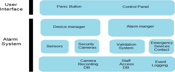
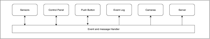
Figure 1 �C Bank security system layered architecture model [2]. 4.1.2 Event Driven ModelThere are three major parts of the system that will produce events that have an effect on the running of the system. These are sensors which can cause an alarm to trigger during the night state, the push button which will trigger an emergency state during the day state and the control panel which will signal a change from night to day state. All other components of the system make some use of the event signals produced by these three to perform certain functions.
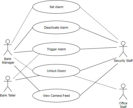
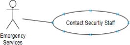
Figure 2 �C Bank security system event driven architecture model [4]. 4.2 Use Case DiagramThe following use case diagram shows the major stakeholders for this system as well as how they can interact with this system. All staff will be able to unlock doors for a small duration with the use of a keycard. Bank tellers will also be able to trigger a silent alarm during the day state with the use of a push button. Both the managers and security staff of the bank will be able to interact with all aspects of the system to differing degrees. Emergency services will also use the system by contacting the security staff to open doors for access when they are ready to enter the bank.
Figure 3 �C Bank security system use case diagram [2]. 4.3 Component Diagram
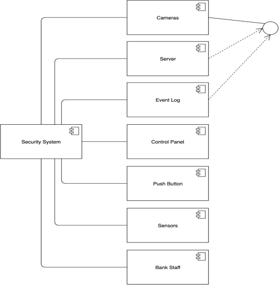
Figure 4 �C Bank security system component diagram [3]. 4.4 Class DiagramThe class diagram shows a more in depth version of the components of the system and some other supporting objects used by the system [1,2]. The activation and deactivation of sensors is dependent on the arming of the system through the control panel. The control panel is also used to trigger a change in the system state object which also controls whether or not the push buttons are active. The server also makes use of camera and bank staff objects to send camera feed to the phones of relevant staff while the system is in night mode. The slight differences in usability of the system for the different staff members is also shown such as the security guard being the sole person who can open all doors at once so that they can operate with emergency services.
|
||||||||||||||||||||||||||||||||||||||||||||||||||||||||||
| |
|