perimental and analytical investigations are required to link the shear contribution of FRP with the load condition. These studies have to consider both the longitudinal steel reinforcement ratio and the concrete strength as parameters. Laboratory specimens should maintain practical dimensions.
�� The strengthening effectiveness of FRP has to be addressed in the cases of short and very short shear spans in which arch action governs failure.
�� The interaction between the contribution of external FRP and internal steel shear reinforcement has to be investigated.
�� To optimize design algorithms, additional specimens need to be tested with different CFRP amount and configurations to create a large database of information.
�� Shear design algorithms need to be expanded to include strengthening with aramid FRP and glass FRP sheets in addition to CFRP.
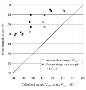
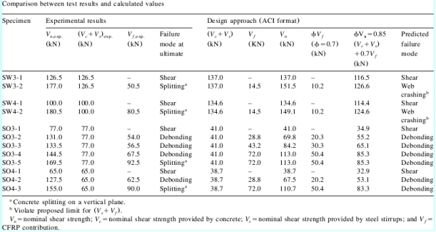
Fig. 13. Comparison between experimental and calculated values of shear strength for the strengthened beams.
6. Nomenclature
A: Shear span
 :Area of CFRP shear reinforcements=2t f w f
 : Width of the beam cross-section
D: Depth from the top of the section to the tension steel reinforcement centroid
 :Effective depth of the CFRP shear reinforcement (usually equal to d for rectangular sections and dyts for T-sections)
 :Elastic modulus of FRP (GPa)
 :Nominal concrete compressive strength (MPa)
 :Effective tensile stress in the FRP sheet in the direction of the principal fibers (stress level in the FRP at failure)
 :Ultimate tensile strength of the FRP sheet in the direction of the principal fibers
 :Effective bond length (mm)
R: Reduction coefficient (ratio of effective average stress or strain in the FRP sheet to its ultimate strength or elongation)
 :Spacing of FRP strips
 :Thickness of the FRP sheet on one side of the beam (mm)
 :Nominal shear strength provided by concrete
 :Nominal shear strength provided by FRP shear reinforcement (ACI format)
 :Nominal shear strength (ACI format)
 :Nominal shear strength provided by steel shear reinforcement (ACI format)
 : Design shear contribution of CFRP to the shear capacity (Eurocode format)
 : Design shear capacity of concrete (Eurocode format)
 :Maximum design shear force that can be carried without web failure (Eurocode format)
 : Design contribution of steel shear reinforcement (Eurocode format)
 :Width of FRP strip
 :Effective width of FRP sheet (mm)
 : Angle between the principal fiber orientation and the longitudinal axis of the beam
 :Effective strain of FRP
 : Ultimate tensile elongation of the fiber material in the FRP composite
 : Strength reduction factor (ACI format)
 :Partial safety factor for CFRP materials (Eurocode format)
 :FRP area fractions(2t f yb w ) (w f ys f)
Acknowledgments
This work was conducted with partial support from the University Transportation Center on Advanced Mate-rials and Non-Destructive Testing (NDT) Technologies based at the University of Missouri, Rolla. The Egyptian Cultural and Educational Bureau, Washington, DC, provided support to the first author.
References
[1] Uji K. Improving shear capacity of existing reinforced concrete members by applying carbon fiber sheets. Trans Jpn Concr Institute 1992;14:253�C66.
[2] Al-Sulaimani GJ, Sharif A, Basunbul IA, Baluch MH, Ghaleb BN. Shear repair for reinforced concrete by fiberglass plate bonding. ACI Struct J 1994;91(3):458�C64.
[3] Chajes MJ, Januska TF, Mertz DR, Thomson TA, Finch WW. Shear strengthening of reinforced concrete beams using externally applied composite fabrics. ACI Struct J 1995;92(3):295�C303.
[4] Arduini M, Nanni A, Di Tommaso A, Focacci F. Shear response of continuous RC beams strengthened with carbon fRP sheets. Proceedings of the Third Symposium on Non-Metallic (FRP) Reinforcement for Concrete Structures, vol. 1. Japan, October 1997:459�C466.
[5] Taerwe L, Khalil H, Matthys S. Behavior of RC beams strengthened in shear by external CFRP sheets. Proceedings of the Third Symposium on Non-Metallic (FRP) Reinforcement for Concrete Structures, vol. 1. Japan, October 1997:483�C490.
[6] Sato Y, Ueda T, Kakuta Y, Tanaka T. Ultimate shear capacity of reinforced concrete beams with carbon fiber sheets. Proceedings of the Third Symposium on Non-Metallic (FRP) Reinforcement for Concrete Structures, vol. 1. Japan, October1997:499�C506.
[7] Triantafillou TC. Shear strengthening of reinforced concrete, beams using epoxy-bonded FRP composites. ACI Struct J 1998;95(2):107�C15.
[8] Nawy E. Reinforced concrete��a fundamental approach.Engle-wood Cliffs, New Jersey: Prentice-Hill, Inc, 1985. (701 p).
[9] Khalifa A, Tumialan G, Nanni A, Belarbi A. Shear strength-ening of continuous RC beams using externally bonded CFRP sheets. Fourth International Symposium on Fiber Reinforced Polymer for Reinforced Concrete Structures (FRPRCS-4). October 1999:995�C1008.
[10] Khalifa A. Shear performance of beams strengthened with advanced composites. Ph.D. thesis. Alexandria University, Egypt: Structural Engineering Department, 1999.
[11] Khalifa A, Alkhrdaji T, Nanni A, Lansburg A. Anchorage of surface mounted FRP reinforcement. Concr Int ACI 1999;49�C54.
[12] ACI Committee 318. Building code requirements for structural concrete (ACI 318�C95) and commentary (ACI 318R-95). Detroit: American Concrete Institute, 1995. (369 pp).
[13] Khalifa A, Gold W, Nanni A, Abdel-Aziz MI. Contribution of externally bonded FRP to the shear capacity of RC flexural members. J Compos Constr ASCE 1998;2(4):195�C202.
[14] Miller, Brian D., 1999. Bond between carbon fiber reinforcedpolymer sheets and concrete. M.Sc. thesis. Rolla, MO, USA: Department of Civil Engineering, The University of Missouri, 1999.
[15] Eurocode no. 2, design of concrete structures. Lausanne: European Committee for Standardization, 1992.
, Rehabilitation of rectangular simply supported RC beams with shear deficiencies using CFRP composites
Ahmed Khalifa a,* , Antonio Nanni b
a Department of Structural Engineering, University of Alexandria, Alexandria 21544, Egypt
bDepartment of Civil Engineering, University of Missouri at Rolla, Rolla, MO 65409, USA
Received 28 April 1999; received in revised form 30 October 2001; accepted 10 January 2002
Abstract
The present study examines the shear performance and modes of failure of rectangular simply supported reinforced concrete(RC) beams designed with shear deficiencies. These members were strengthened with externally bonded carbon fiber reinforced polymer (CFRP) sheets and evaluated in the laboratory. The experimental program consisted of twelve full-scale RC beams tested to fail in shear. The variables investigated within this program included steel stirrups, and the shear span-to-effective depth ratio, as well as amount and distribution of CFRP. The experimental results indicated that the contribution of externally bonded CFRP to the shear capacity was significant. The shear capacity was also shown to be dependent upon the variables investigated. Test results were used to validate a shear design approach, which showed conservative and acceptable predictions.C 2002 Elsevier Science Ltd. All rights reserved.
Keywords: Rehabilitation; Shear; Carbon fiber reinforced polymer
1. Introduction
Fiber reinforced polymer (FRP) composite systems, composed of fibers embedded in a polymeric matrix, can be used for shear strengthening of reinforced con-crete (RC) members [1�C7]. Many existing RC beams are deficient and in need of strengthening. The shear failure of an RC beam is clearly different from its flexural failure. In shear, the beam fails suddenly without sufficient warning and diagonal shear cracks are consid-erably wider than the flexural cracks [8].
The objectives of this program were to:
1. Investigate performance and mode of failure of simply supported rectangular RC beams with shear deficien-cies after strengthening with externally bonded CFRP sheets.
2. Address the factors that influence shear capacity of strengthened beams such as: steel stirrups, shear span-to-effective depth ratio (a/d ratio), and amount and distribution of CFRP.
3. Increase the experimental database on shear strength-ening with externally bonded FRP reinforcement.
4. Validate the design approach previously proposed by the authors [9].
For these objectives, 12 full-scale, RC beams designed to fail in shear were strengthened with different CFRP schemes. These members were tested as simple beams using a four-point loading configuration with two different a/d ratios.
2. Experimental program
2.1. Test specimens and materials
Twelve full-scale beam specimens with a total span of 3050 mm. and a rectangular cross-section of 150-mm-wide and 305-mm-deep were tested. The specimens were grouped into two main series designated SW and SO depending on the presence of steel stirrups in the shear span of interest.
Series SW consisted of four specimens. The details and dimensions of the specimens designated series SW are illustrated in Fig. 1a. In this series, four 32-mm steel bars were used as longitudinal reinforcement with two at top and two at bottom face of the cross-section to induce a shear failure. The specimens were reinforced with 10-mm steel stirrups throughout their entire span. The stirrups spacing in the shear span of interest, right half, was selected to allow failure in that span.
Series SO consisted of eight beam specimens, which had the same cross-section dimension and longitudinal steel reinforcement as for series SW. No stirrups were provided in the test half span as illustrated in Fig. 1b.
Each main series (i.e. series SW and SO) was subdivided into two subgroups according to shear span-to-effective depth ratio. This was selected to be a/d = 3 and 4, resulting in the following four subgroups: SW3;SW4; SO3; and SO4.
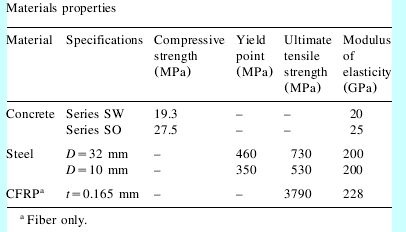
The mechanical properties of the materials used for manufacturing the test specimens are listed in Table 1.Fabrication of the specimens including surface preparation and CFRP installation is described elsewhere [10].
Table 1
2.2. Strengthening schemes
One specimen from each series (SW3-1, SW4-1, SO3-1 and SO4-1) was left without strengthening as a control specimen, whereas eight beam specimens were strengthened with externally bonded CFRP sheets following three different schemes as illustrated in Fig. 2.
In series SW3, specimen SW3-2 was strengthened with two CFRP plies having perpendicular fiber directions (90��/0��). The first ply was attached in the form of continuous U-wrap with the fiber direction oriented perpendicular to the longitudinal axis of the specimen (90��). The second ply was bonded on the two sides of the specimen with the fiber direction parallel to the beam axis��0�㣩.This ply [i.e. 0��ply] was selected to investigate the impact of additional horizontal restraint on shear strength.
In series SW4, specimen SW4-2 was strengthened with two CFRP plies having perpendicular fiber direction (90��/0��) as for specimen SW3-2.
Four beam specimens were strengthened in series SO3. Specimen SO3-2 was strengthened with one-ply CFRP strips in the form of U-wrap with 90��-fiber orientation. The strip width was 50 mm with center-to-center spacing of 125 mm. Specimen SO3-3 was strengthened in a manner similar to that of specimen SO3-2, but with strip width equal to 75 mm. Specimen SO3-4 was strengthened with one-ply continuous U-wrap (90��). Specimen SO3-5 was strengthened with two
CFRP plies (90��/0��) similar to specimens SW3-2 and SW4-2.
In series SO4, two beam specimens were strengthened. Specimen SO4-2 was strengthened with one-ply CFRP strips in the form of U-wrap similar to specimen SO3-2. Specimen SO4-3 was strengthened with one-ply continuous U-wrap (90��) similar to SO3-4.
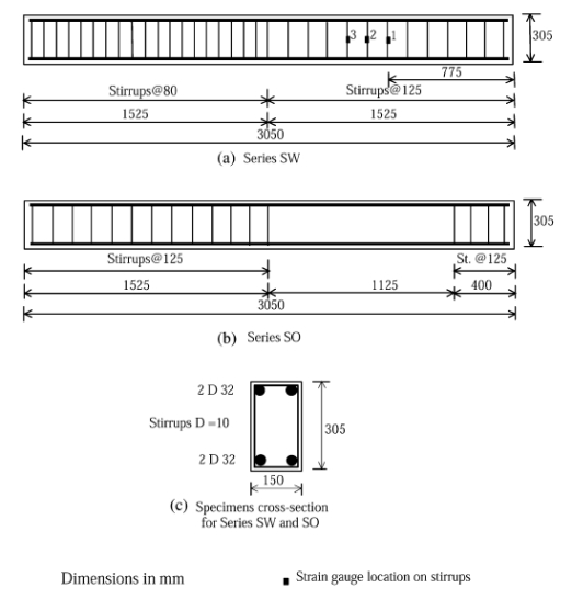
Fig. 1. Configuration and reinforcement details for beam specimens.
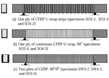
Fig. 2. Schematic representation of CFRP strengthening schemes.
2.3. Test set-up and instrumentation
All specimens were tested as simple span beams subjected to a four-point load as illustrated in Fig. 3. A universal testing machine with 1800 KN capacity was used in order to apply a concentrated load on a steel distribution beam used to generate the two concentrated loads. The load was applied progressively in cycles, usually one cycle before cracking followed by three cycles with the last one up to ultimate. The applied load vs. deflection curves shown in this paper are the envelopes of these load cycles.
Four linear variable differential transformers (LVDTs) were used for each test to monitor vertical displacements at various locations as shown in Fig. 3. Two LVDTs were located at mid-span on each side of the specimen. The other two were located at the specimen supports to record support settlement.
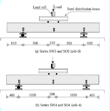
Fig.3. Schematic representation of test set-up for specimen (a) SW3-1, and (b) SW3-2.
For each specimen of series SW, six strain gauges were attached to three stirrups to monitor the stirrup strain during loading as illustrated in Fig. 1a. Three strain gauges were attached directly to the FRP sheet on the sides of each strengthened beam to monitor strain variation in the FRP. The strain gauges were oriented in the vertical direction and located at the section mid-height with distances of 175, 300 and 425 mm, respectively, from the support for series SW3 and SO3. For beam specimens of series SW4 and SO4, the strain gauges were located at distance of 375, 500 and 625 mm, respectively, from the support.
3. Results and discussion
In the following discussion, reference is always made to weak shear span or span of interest.
3.1. Series SW3
Shear cracks in the control specimen SW3-1 were observed close to the middle of the shear span when the load reached approximately 90 kN. As the load increased, additional shear cracks formed throughout, widening and propagating up to final failure at a load of 253 kN (see Fig. 4a).
In specimen SW3-2 strengthened with CFRP (90��/0��), no cracks were visible on the sides or bottom of the test specimen due to the FRP wrapping. However��a longitudinal splitting crack initiated on the top surface of the beam at a high load of approximately 320 kN.
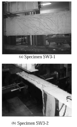
Fig. 4. Failure modes of series SW3 specimens.
The crack initiated at the location of applied load and extended towards the support. The specimen failed by concrete splitting (see Fig. 4b) at total load of 354 kN. This was an increase of 40% in ultimate capacity compared to the control specimen SW3-1. The splitting failure was due to the relatively high longitudinal compressive stress developed at top of the specimen, which created a transverse tension, led to the splitting failure. In addition, the relatively large amount of longitudinal steel reinforcement combined with over-strengthening for shear by CFRP wrap probably caused this mode of failure. The load vs. mid-span deflection curves for specimens SW3-1 and SW3-2 are illustrated in Fig. 5, to show the additional capacity gained by CFRP.
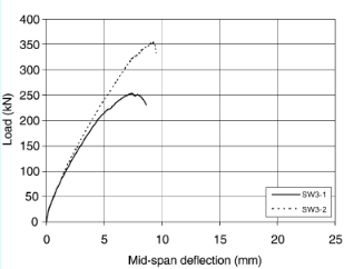
Fig. 5. Applied load vs. mid-span deflection for series SW3 specimens.
The maximum CFRP vertical strain measured at failure in specimen SW3-2 was approximately 0.0023 mm/mm, which corresponded to 14% of the reported CFRP ultimate strain. This value is not an absolute because it greatly depends on the location of the strain gauges with respect to a crack. However, the recorded strain indicates that if the splitting did not occur, the shear capacity could have reached higher load.
Comparison between measured local stirrup strains in specimens SW3-1 and SW3-2 are shown in Fig. 6. The stirrups 1, 2 and 3 were located at distance of 175, 300 and 425 mm from the support, respectively. The results showed that the stirrups 2 and 3 did not yield at ultimate for both specimens. The strains (and the forces) in the stirrups of specimen SW3-2 were, in general, smaller than those of specimen SW3-1 at the same level of loading due to the effect of CFRP.
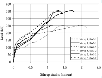
Fig. 6. Applied load vs. strain in the stirrups for specimens SW3-1 and SW3-2.
3.2. Series SW4
In specimen SW4-1, the first diagonal crack was formed in the member at a total applied load of 75 kN. As the load increased, additional shear cracks appeared throughout the shear span. Failure of the beam occurred when the total applied load reached 200 kN. This was a decrease of 20% in shear capacity compared to the specimen SW3-1 with a/d ratio=3.
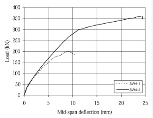
Fig. 7. Applied load vs. mid-span deflection for series SW4 specimens.
In specimen SW4-2, the failure was controlled by concrete splitting similar to test specimen SW3-2. The total applied load at ultimate was 361 kN with an 80% increase in shear capacity compared to the control specimen SW4-1. In addition, the measured strains in the stirrups for specimen SW4-2 were less than those of specimen SW4-1. The applied load vs. mid-span deflection curves for beams SW4-1 and SW4-2 are illustrated in Fig. 7. It may be noted that specimen SW4-2 resulted in greater deflection when compared to specimen SW4-1.
When comparing the test results of series SW3 specimens to that of series SW4, the ultimate failure load of specimen SW3-2 and SW4-2 was almost the same. However, the enhanced capacity of specimen SW3-2 (a/d=3) due to the addition of the CFRP reinforcement was 101 kN, while specimen SW4-2 (a/d=4) was 161 kN. This indicates that the contribution of external CFRP reinforcement may be influenced by the ayd ratio and appears to decrease with a decreasing a/d ratio. Further, for both strengthened specimens (SW3-2 and SW4-2), CFRP sheets did not fracture or debond from the concrete surface at ultimate and this indicates that CFRP could provide additional strength if the beams did not failed by splitting.
3.3. Series SO3
Fig. 8 illustrates the failure modes for series SO3 specimens. Fig. 9 details the applied load vs. mid-span deflection for the specimens.
The failure mode of control specimen SO3-1 was shear compression. Failure of the specimen occurred at a total applied load of 154 kN. This load was a decrease of shear capacity by 54.5 kN compared to the specimen SW3-1 due to the absent of the steel stirrups. In addition, the crack pattern in specimen SW3-1 was different from of specimen SO3-1. In specimen SW3-1, the presence of stirrups provided a better distribution of diagonal cracks throughout the shear span.
In specimen SO3-2, strengthened with 50-mm CFRP strips spaced at 125 mm, the first diagonal shear crack was observed at an applied load of 100 kN. The crack propagated as the load increased in a similar manner to that of specimen SO3-1. Sudden failure occurred due to debonding of the CFRP strips over the diagonal shear crack, with spalled concrete attached to the CFRP strips. The total ultimate load was 262 kN with a 70% increase in shear capacity over the control specimen SO3-1. The maximum local CFRP vertical strain measured at failure in specimen SO3-2 was 0.0047 mm/mm (i.e. 28% of the ultimate strain), which indicated that the CFRP did not reach its ultimate.
Specimen SO3-3, strengthened with 75-mm CFRP strips failed as a result of CFRP debonding at a total applied load of 266 kN. No significant increase in shear capacity was noted compared to specimen SO3-2. The maximum-recorded vertical CFRP strain at failure was 0.0052 mmymm (i.e. 31% of the ultimate strain).
Specimen SO3-4, which was strengthened with a continuous CFRP U-wrap (908), failed as a result of CFRP debonding at an applied load of 289 kN. Results show that specimen SO3-4 exhibited increase in shear capacity of 87, 10 and 8.5% over specimens SO3-1,
SO3-2 and SO3-3, respectively. Applied load vs. vertical CFRP strain for specimen SO3-4 is illustrated in Fig. 10 in which strain gauges sg1, sg2 and sg3 were located at mid-height with distances of 175, 300 and 425 mm from the support, respectively. Fig. 10 shows that the CFRP strain was zero prior to diagonal crack formation, then increased slowly until the specimen reached a load in the neighborhood of the ultimate strength of the control specimen. At this point, the CFRP strain increased significantly until failure. The maximum local CFRP vertical strain measured at failure was approxi- mately 0.0045 mm/mm.
When comparing the results of beams SO3-4 and SO3-2, the CFRP amount used to strengthen specimen SO3-4 was 250% of that used for specimen SO3-2. Only a 10% increase in shear capacity was achieved for the additional amount of CFRP used. This means that if an end anchor to control FRP debonding is not used, there is an optimum FRP quantity, beyond which the strengthening effect is questionable. A previous study [11] showed that by using an end anchor system, the failure mode of FRP debonding could be avoided. Reported findings are consistent with those of other research [7], which was based on a review of the experimental results available in the literature, and indicated that the contribution of FRP to the shear capacity increases almost linearly, with FRP axial rigidity expressed by  (
( is the FRP area fraction and
  is the FRP elastic modulus) up to approximately 0.4 GPa. Beyond this value, the effectiveness of FRP ceases to be positive.
In specimen SO3-5, the use of a horizontal ply over the continuous U-wrap (i.e. 90��/0��) resulted in a concrete splitting failure rather than a CFRP debonding failure. The failure occurred at total applied load of 339 kN with a 120% increase in the shear capacity compared to the control specimen SO3-1. The strengthening with two perpendicular plies (i.e. 90��/0��) resulted in a 17% increase in shear capacity compared to the specimen with only one CFRP ply in 90�� orientation (i.e. specimen SO3-4). The maximum local CFRP vertical strain measured at failure was 0.0043 mm/mm.
By comparing the test results of specimens SW3-2 and SO3-5, having the same a/d ratio and strengthening schemes but with different steel shear reinforcement, the shear strength (i.e. 177 and 169.5 kN for specimens SW3-2 and SO3-5, respectively), and the ductility are almost identical. One may conclude that the contribution of CFRP benefits the beam capacity to a greater degree for beams without steel shear reinforcement than for beams with adequate shear reinforcement.
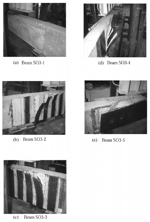
Fig. 8. Failure modes of series SO3 specimens.
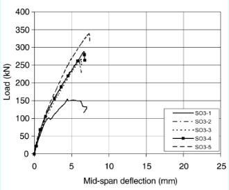
Fig. 9. Applied load vs. mid-span deflection for series SO3 specimens.
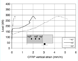
Fig. 10. Measured vertical CFRP strain for specimen SO3-4.
3.4. Series SO4
Series SO4 exhibited the largest increase in shear capacity compared to the other series investigated with this research study. The experimental results in terms of applied load vs mid-span deflection for this series is illustrated in Fig. 11.
The control specimen SO4-1 failed as a result of shear compression at a total applied load of 130 kN. Specimen SO4-2, strengthened with CFRP strips, the failure was controlled by CFRP debonding at a total load of 255 kN with 96% increase in shear capacity over the control specimen SO4-1. The maximum local CFRP vertical strain measured at failure was 0.0062
mmymm.
When comparing the test results of specimen SO4-2 to that of specimen SO3-2, the enhanced shear capacity of specimen SO4-2 (a/d=4) due to addition of CFRP strips was 62.5 kN, while specimen SO3-2 (a/d=3) resulted in added shear capacity of 54 kN. As expected, the contribution of CFRP reinforcement to resist the shear appeared to decrease with decreasing a/d ratio. Specimen SO4-3, strengthened with continuous U- wrap, failed as a result of concrete splitting at an applied load of 310 kN with a 138% increase in shear capacity compared to that of specimen SO4-1. The maximum local CFRP vertical strain measured at failure was 0.0037 mm/mm.
4. Design approach
The design approach for computing the shear capacity of RC beams strengthened with externally bonded CFRP reinforcement, expressed in ACI design code [12] format, was proposed and published in 1998 [13]. The design model described two possible failure mechanisms of CFRP reinforcement namely: CFRP fracture; and CFRP debonding. Furthermore, two limits on the contribution of CFRP shear were proposed. The first limit was set to control the shear crack width and loss of aggregate interlock, and the second was to preclude web crushing. Also, the concrete strength and CFRP wrap- ping schemes were incorporated as design parameters. In recent study [9,10], modifications were proposed to the 1998 design approach to include results of a new study on bond mechanism between CFRP sheets and concrete surface [14]. In addition, the model was extended to provide the shear design equations in Eurocode as well as ACI format. Comparing with all test results available in the literature to date, 76 tests, the design approach showed acceptable and conservative estimates [10,13]. In this section, the summary of the design approach is presented. The comparison between experimental results and the calculated factored shear strength demonstrates the ability of the design approach to predict the shear capacity of the strengthened beams. demonstrates the ability of the design approach to predict the shear capacity of the strengthened beams.
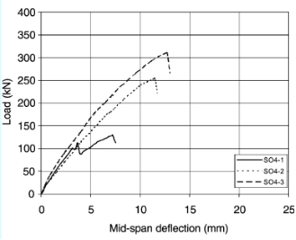
Fig. 11. Applied load vs. mid-span deflection for series SO4 specimens.
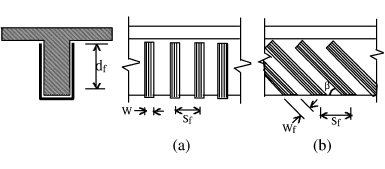
Fig. 12. Dimensions used to define the area of FRP (a) vertical oriented FRP strips, and (b) inclined strips.
4.1. Summary of the shear design approach �� ACI format
In traditional shear design (including the ACI Code), the nominal shear strength of an RC section is the sum of the nominal shear strengths of concrete and steel shear reinforcement. For beams strengthened with externally bonded FRP reinforcement, the shear strength may be computed by the addition of a third term to account of the FRP contribution. This is expressed as follows:

The design shear strength, , is obtained by multiplying the nominal shear strength by a strength reduction factor for shear,
 . It was suggested that the reduction factor
  =0.85 given in ACI [12] be main-tained for the concrete and steel terms. However, a more stringent strength reduction factor of 0.7 for the CFRP contribution was suggested w10x. This is due to the relative novelty of this repair technique. Thus, the design shear strength is expressed as follows.

4.2. Contribution of CFRP reinforcement to the shear capacity
The expression used to compute shear contribution of CFRP reinforcement is given in Eq. (3). This equation is similar to that for shear contribution of steel stirrups and consistent with the ACI format.
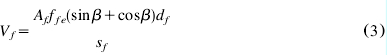
The area of CFRP shear reinforcement,  , is the total thickness of the sheet (usually
  or sheets on both sides of the beam) times the width of the CFRP strip
  . The dimensions used to define the area of CFRP in addition to the spacing
  and the effective depth of CFRP,
 �� are shown in Fig. 12. Note that for continuous vertical shear reinforcement, the spacing of the strip,
 , and the width of the strip,
  , are equal.
In Eq. (3), an effective average CFRP stress , smaller than its ultimate strength,
 , was used to replace the yield stress of steel. At the ultimate limit state for the member in shear, it is not possible to attain the full strength of the FRP [7,13]. Failure is governed by either fracture of the FRP sheet at average stress levels well below FRP ultimate capacity due to stress concentrations, debonding of the FRP sheet from the concrete surface, or a significant decrease in the post- cracking concrete shear strength from a loss of aggregate interlock. Thus, the effective average CFRP stress is computed by applying a reduction coefficient, R, to the CFRP ultimate strength as expressed in Eq. (4).

The reduction coefficient depends on the possible failure modes (either CFRP fracture or CFRP debonding). In either case, an upper limit for the reduction coefficient is established in order to control shear crack width and loss of aggregate interlock.
4.3. Reduction coefficient based on CFRP sheet fracture failure
The proposed reduction coefficient was calibrated on all available test results to date, 22 tests with failure controlled by CFRP fracture [10��13]. The reduction coefficient was established as a function of (where
  is the area fraction of CFRP) and expressed in Eq.(5) for
  0.7 GPa.

4.4. Reduction coefficient based on CFRP debonding failure
The shear capacity governed by CFRP debonding from the concrete surface was presented [9,10]as a function of CFRP axial rigidity, concrete strength, effective depth of CFRP reinforcement, and bonded surface configurations. In determining the reduction coefficient for bond, the effective bond length,  , has to be determined first. Based on analytical and experimental data from bond tests, Miller [14] showed that the effective bond length slightly increases as CFRP axial rigidity,
 , increases. However, he suggested a constant conservative value
  for equal to 75 mm. The value may be modified when more bond tests data becomes available.
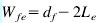
After a shear crack develops, only that portion of the width of CFRP extending past the crack by the effective bonded length is assumed to be capable of carrying shear.[13] The effective width,  , based on the shear crack angle of 45��, and the wrapping scheme is expressed in Eqs. (6a) and (6b);
 if the sheet in the form of a U-wrap (6a)
 if the sheet is bonded only to the sides of the beam. (6b)
The final expression for the reduction coefficient, R, for the mode of failure controlled by CFRP debonding is expressed in Eq. (8)
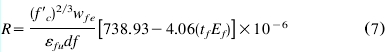
Eq. (7) is applicable for CFRP axial rigidity,  , ranging from 20 to 90 mm-GPa (kN/mm). Research into quantifying the bond characteristics for axial rigidities above 90 mm��GPa is being conducted at the University of Missouri, Rolla (UMR).
4.5. Upper limit of the reduction coefficient
In order to control the shear crack width and loss of aggregate interlock, an upper limit of reduction coefficient, R, was suggested and calibrated with all of the available test results [10] to be equal to  where
where  is the ultimate tensile CFRP strain. This limit is such that the average effective strain in CFRP materials at ultimate can not be greater than 0.006 mm/mm (without the strengthening reduction factor,
 ).
).
4.6. Controlling reduction coefficient
The final controlling reduction coefficient for the CFRP system is taken as the lowest value determined from the two possible modes of failure and the upper limit. Note that if the sheet is wrapped entirely around the beam or an effective end anchor is used, the failure mode of CFRP debonding is not to be considered. The reduction coefficient is only controlled by FRP fracture and the upper limit.
4.7. CFRP spacing requirements
Similar to steel shear reinforcement, and consistent with ACI provision for the stirrups spacing [12], the spacing of FRP strips should not be so wide as to allow the formation of a diagonal crack without intercepting a strip. For this reason, if strips are used, they should not be spaced by more than the maximum given in Eq. (8).

4.8. Limit on total shear reinforcement
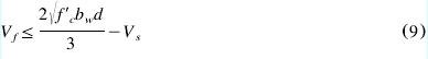
ACI 318M-95 [12] 11.5.6.7 and 11.5.6.8 set a limit on the total shear strength that may be provided by more than one type of shear reinforcement to preclude the web crushing. FRP shear reinforcement should be included in this limit. A modification to ACI 318M-95 Section 11.5.6.8 was suggested as follows:
4.9. Shear capacity of a CFRP strengthened section �� Eurocode format
The proposed design equation wEq. (3)x for computing the contribution of externally bonded CFRP reinforcement may be rewritten in Eurocode (EC2 1992) [15] format as Eq. (10).
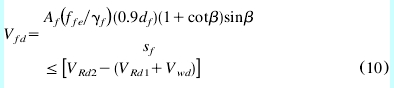
In this equation, the partial safety factor for CFRP materials, , was suggested equal to 1.3 [10].
4.10. Comparison between the test results and calculated values
The test summary and the comparison between the test results and the calculated shear strength, using the design approach (ACI format), are detailed in Tables 2 and 3, respectively. For CFRP strengthened beams, the measured contribution of concrete, Vc , and steel stirrups, Vs, (when present) were considered equal to the shearstrength of a non-strengthened beam. The nominal shear strength provided by concrete and steel stirrups was computed using Equations (11-5) and (11-15) in ACI- 318-95 [12]. In Equation (11-5), the values of Vu and M u were taken at the point of application of the load. The comparison indicates that the design approach gives conservative results for the strengthened beams as illus-trated in Fig. 13.
5. Conclusions and further recommendation
An experimental investigation was conducted to study the shear behavior and the modes of failure of simply supported rectangular section RC beams with shear deficiencies, strengthened with CFRP sheets. The parameters investigated in this program were existence of steel shear reinforcement, shear span-to-effective depth ratio (ayd ratio), and CFRP amount and distribution.
The results confirm that the strengthening technique using CFRP sheets can be used to increase significantly shear capacity, with efficiency that varies depending on the tested variables. For the beams tested in this program, increases in shear strength of 40�C138% were achieved.
Conclusions that emerged from this study may be summarized as follows:
�� The contribution of externally CFRP reinforcement to the shear capacity is influenced by the a/d ratio.
�� Increasing the amount of CFRP may not result in a proportional increase in the shear strength. The CFRP amount used to strengthen specimen SO3-4 was 250% of that used in specimen SO3-2, which resulted in a minimal (10%) increase in shear capacity. An end anchor is recommended if FRP debonding is to be avoided.
Table2
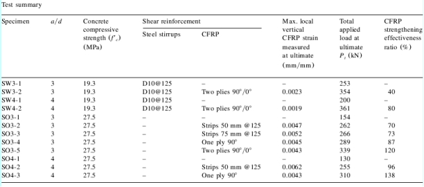
Table3
�� The test results indicated that contribution of CFRP benefits the shear capacity at a greater degree for beams without shear reinforcement than for beams with adequate shear reinforcement.
�� The results of series SO3 indicated that the 0�� ply improved the shear capacity by providing horizontal restraint.
�� The shear design algorithms provided acceptable and conservative estimates for the strengthened beams. Recommendations for future research are as follows:
�� Ex
