摘 要
本文聚焦于基于ESP32S3的嵌入式多功能调试器设计。该调试器整合DAPlink、逻辑分析仪、串口助手等十余种功能,覆盖大部分嵌入式调试场景。硬件上,采用分层架构,以ESP32S3为核心控制器,搭配屏幕、触摸模块等,精心设计功率控制板与信号板,确保稳定运行。软件方面,运用前后台架构,借助VS Code、ARM-GCC等工具链搭建开发环境,实现各功能模块的软件模拟与高效交互。通过搭建完备的测试环境,对硬件功能、性能及软件单元、集成进行全面测试。测试结果表明,该调试器功能完备、性能稳定,能有效满足嵌入式开发中的多样化调试需求,为嵌入式开发者提供便捷、高效的调试工具,对推动嵌入式技术发展具有积极意义。
关键词:ESP32S3;嵌入式多功能调试器;硬件设计;软件实现;系统测试
Abstract
This paper focuses on the design of an embedded multi-functional debugger based on ESP32S3. The debugger integrates more than ten functions, including DAPlink, logic analyzer, and serial port assistant, covering most embedded debugging scenarios. In terms of hardware, a hierarchical architecture is adopted. With ESP32S3 as the core controller, and equipped with a screen, touch module, etc., the power control board and signal board are carefully designed to ensure stable operation. For the software, a foreground-background architecture is used. A development environment is built using tools such as VS Code and ARM-GCC to achieve software simulation and efficient interaction of each functional module. By establishing a comprehensive test environment, thorough tests are conducted on hardware functions, performance, as well as software unit and integration. The test results show that the debugger is fully functional and performs stably, effectively meeting diverse debugging needs in embedded development. It provides embedded developers with a convenient and efficient debugging tool and has positive significance for promoting the development of embedded technology.
Keywords:ESP32S3; Embedded Multi-functional Debugger; Hardware Design; Software Implementation; System Testing
目 录
摘 要
Abstract
第1章 绪论
1.1研究背景及意义
1.1.1 研究背景
1.1.2 研究意义
1.2国内外研究现状
1.2.1国内研究现状
1.2.2国外研究现状
1.3研究主要内容
1.3.1硬件系统设计
1.3.2软件系统实现
1.3.3系统测试与优化
第2章 相关技术与理论基础
2.1 ESP32芯片特性
2.1.1硬件架构与核心处理器性能参数
2.1.2无线通信功能及应用场景
2.1.3外设接口及其作用
2.2 嵌入式调试技术概述
2.2.1嵌入式调试的基本概念与常见方法
2.2.2 DAPlink、逻辑分析仪、串口助手等调试功能的原理
2.2.3多功能调试器整合多种调试技术的优势
2.3 开发环境与工具
2.3.1VS Code开发环境搭建与配置
2.3.2 ARM-GCC与Xtensa-ESP32-ELF工具链的作用与安装
第3章 多功能调试器设计与实现
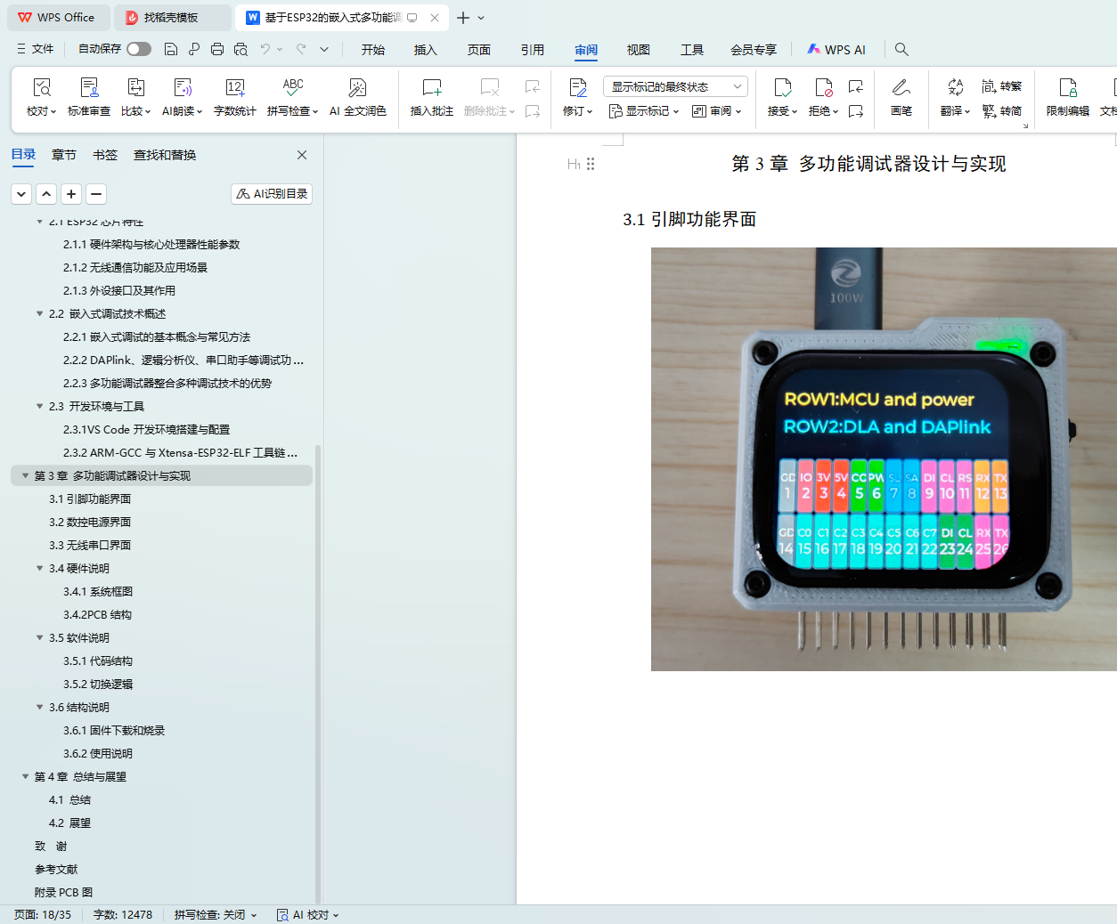
3.1引脚功能界面
3.2数控电源界面
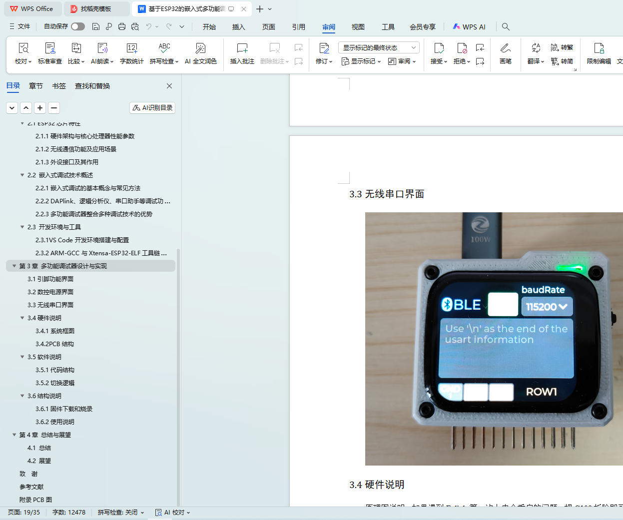
3.3无线串口界面
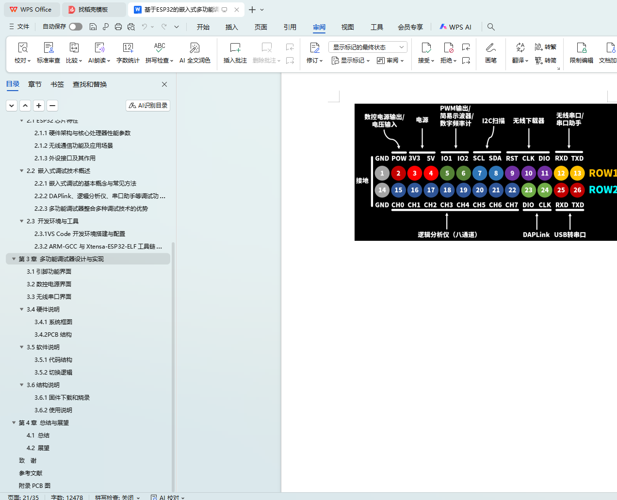
3.4硬件说明
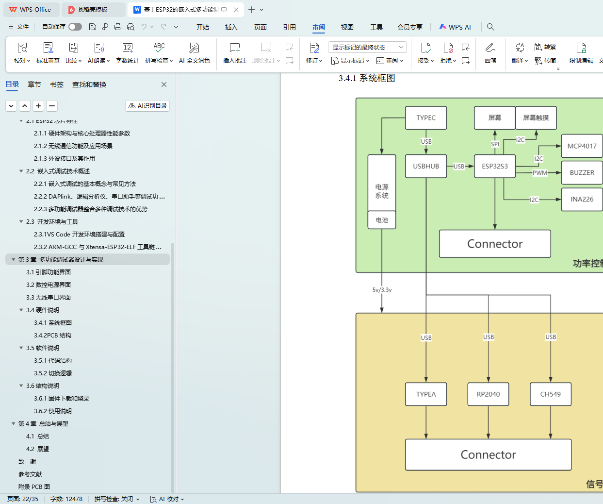
3.4.1系统框图
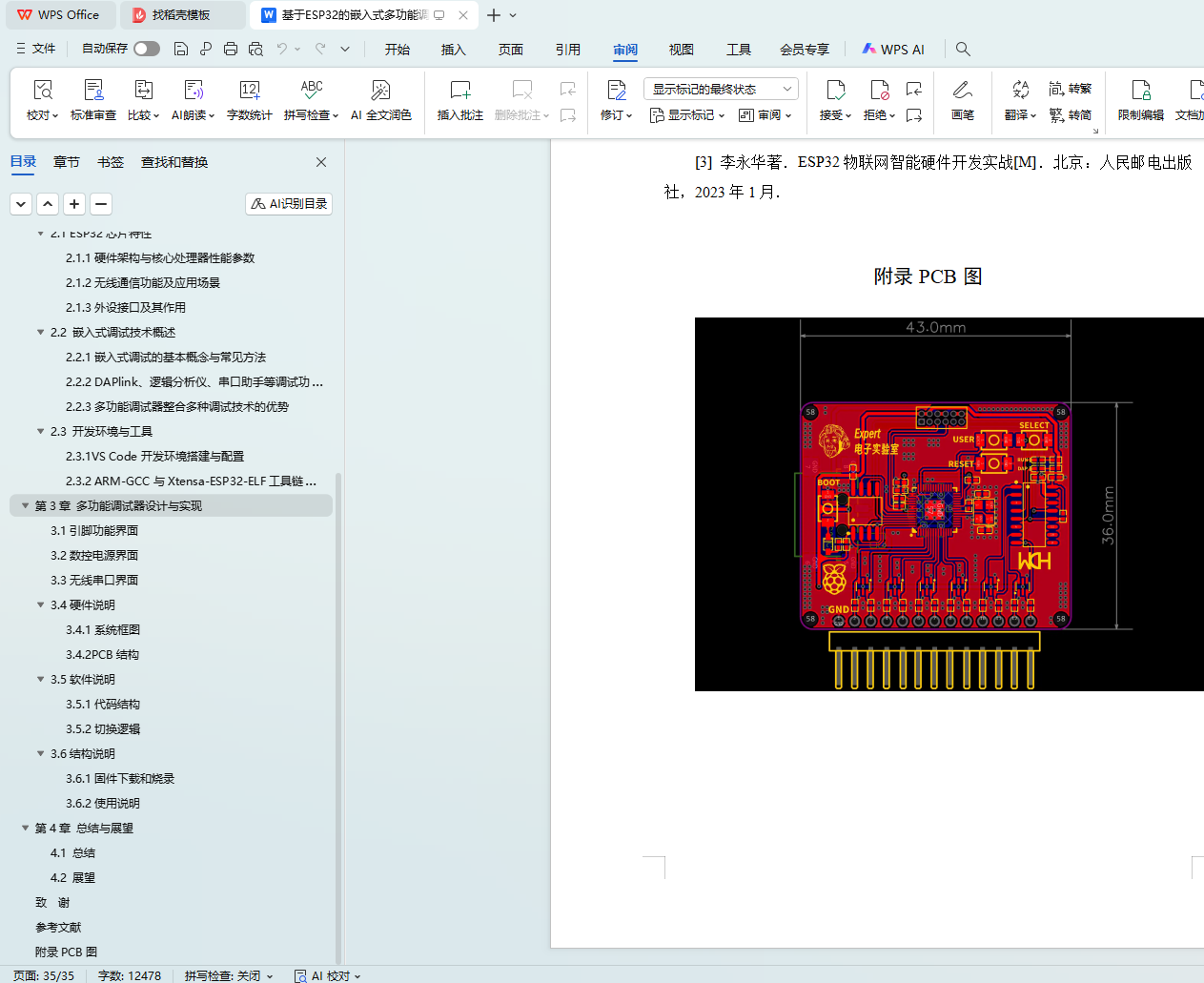
3.4.2PCB结构
3.5软件说明
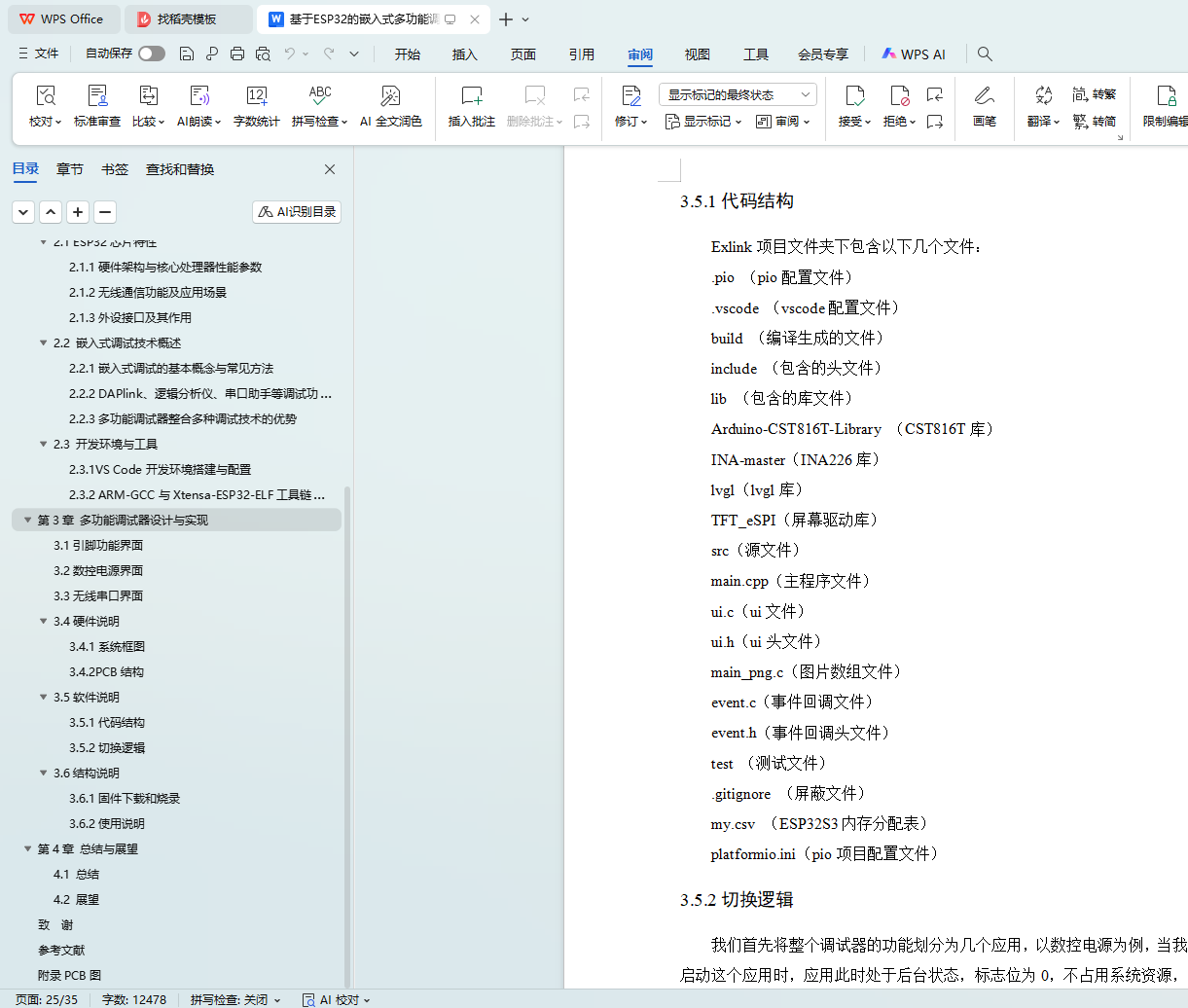
3.5.1代码结构
3.5.2切换逻辑
3.6结构说明
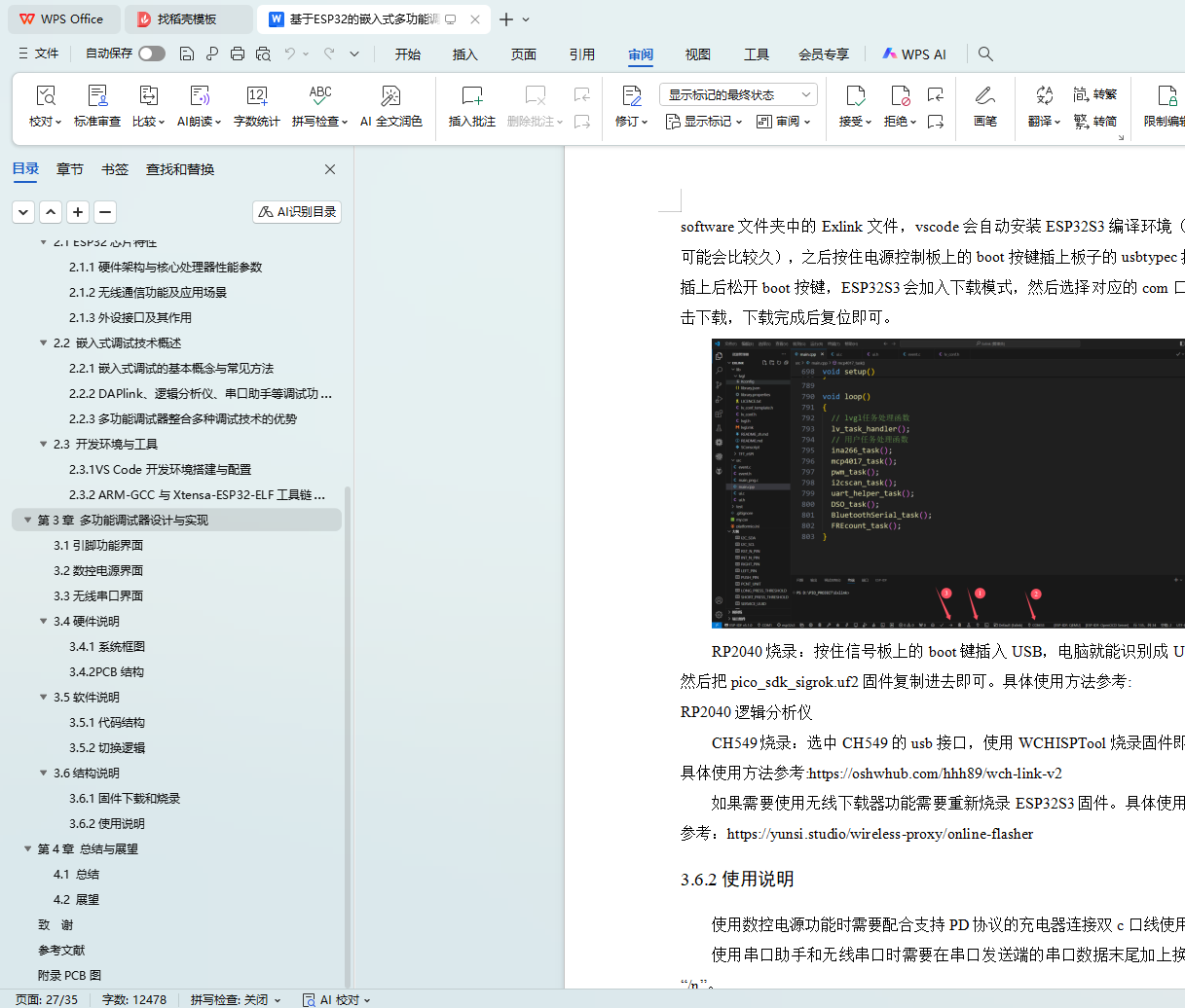
3.6.1固件下载和烧录
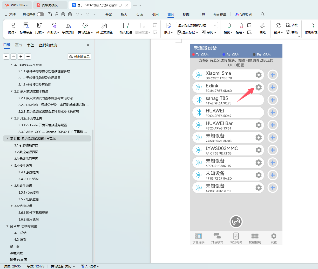
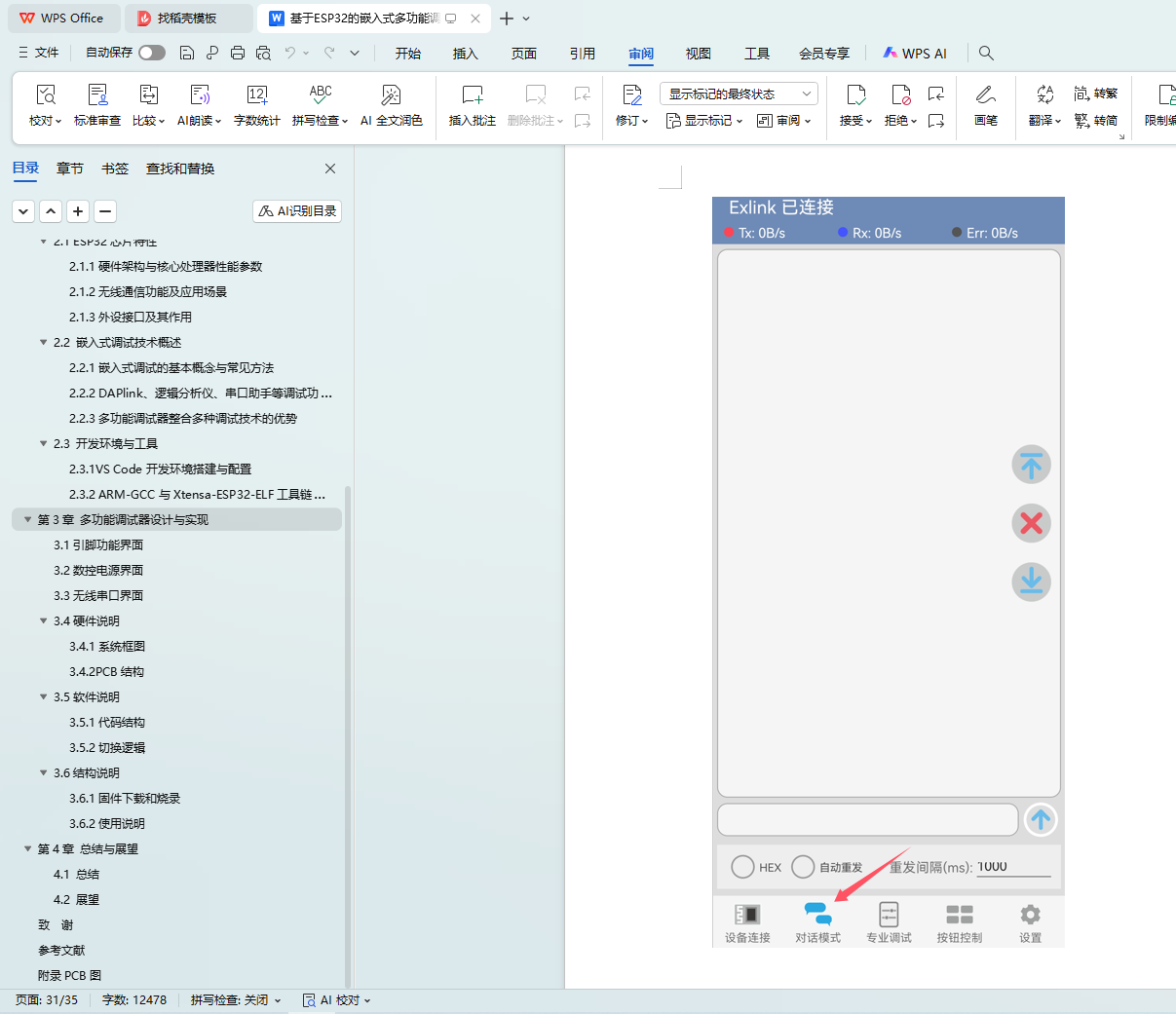
3.6.2使用说明
第4章 总结与展望
4.1 总结
4.2 展望
致 谢
参考文献
附录PCB图